Type 5120
PID BOARD Type 5120
The PID BOARD Type 5120 is a universal training unit for control engineering. It provides the essential functional blocks for introductory and advanced experiments, includes an integrated power supply with pre-trigger control, and can be used on a desk, in a rack or in a transport box.
- Universal training unit for control engineering
- Built-in short-circuit-proof power supply
- All fundamental experiments possible without a storage oscilloscope
- Pre-trigger circuit for complete signal display
- Measurement with oscilloscope, storage oscilloscope or Y-t recorder
- Sequence control with repetition frequencies up to about 100 Hz
Application and measurement concept
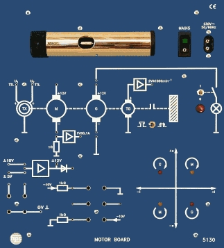
The PID BOARD was developed by hps SystemTechnik specifically for introductory and advanced experiments in control engineering. It can also be used as a controller together with the POWER BOARD Type 5125, the MOTOR BOARD Type 5130, the Temperature and Brightness Controlled System Type 5125.5 and the SERVO BOARD Type 5131.
With only a few exceptions, all control-loop elements with time-dependent behaviour are designed so that their step response can be measured using a standard oscilloscope, a storage oscilloscope or a Y-t recorder. For oscilloscope operation, repetition frequencies of up to about 100 Hz are possible; recorder measurements can be carried out as single events in the seconds range.
Measurement reproducibility and operating comfort are defined by the sequence control specially developed by hps SystemTechnik. Before each cycle, the relevant capacitors are discharged, a pre-trigger circuit ensures complete signal display, and an additional RESET input allows the sequence control to be driven by a computer or PLC.
Functional blocks and adjustment ranges
For each controller, the characteristic values can be adjusted over a wide range using plugs and potentiometers. Signal polarity can be adapted to the overall circuit or the trainer's requirements by different summing, comparison and inversion blocks.
Limit detectors at the controller outputs indicate range violations by LEDs. For the electronic simulation of controlled systems, the board provides an I element, several delay elements and proportional elements.
- Setpoint generator: 0 ... +10 V, 0 ... -10 V and 0 ... +5 V
- Setpoint integrator with continuously adjustable time constant
- Sequence control: 0 ... +10 V, approx. 0 ... 100 Hz, single-shot operation selectable
- Relay with 2 changeover contacts for setpoint, load steps and recorder control
- Comparator 1 and 2 for forming the control deviation e = w - x
- P, I, D and PI controllers, summator, two-step controller and limiter
- 1st-order delay element, 3rd-order delay element and I element
Setup, transport and accessories
For experiments, the PID BOARD can be placed on a desk or mounted in a table rack for demonstration. It can also be screwed into a box for safe transport and storage, while all experiments can still be carried out directly inside the box.
Recommended accessories are the experiment manual “Introduction to Control Engineering” Type V 0120 and the accessory set Type 5120.1 consisting of connecting leads and plugs.
- RESET input for external control by computer or PLC
- Controller parameters adjustable over a wide range via plugs and potentiometers
- Usable together with POWER BOARD, MOTOR BOARD, SERVO BOARD and the temperature/brightness control system
- Detailed experiment descriptions in manual Type V 0120
- Mains connection
- 230 V AC / 115 V AC (110 V AC); 50 ... 60 Hz; 8 VA
- Mechanical design
- 5 mm laminated front panel, matt blue with white symbols; rear side covered by a grey plastic housing
- Board dimensions
- 532 x 297 x 110 mm (W x H x D)
- Board weight
- approx. 3.35 kg
- Box version
- PID BOARD (Type 5120) and box (Type 5120.20)
- Setpoint generator
- Voltages 0 ... +10 V; 0 ... -10 V; 0 ... +5 V
- Setpoint integrator
- Time constant continuously adjustable
- Sequence control
- Voltage 0 ... +10 V; frequency approx. 0 ... 100 Hz; single-shot operation selectable
- Relay
- 2 changeover contacts for setpoint, load steps and recorder control
- Comparator 1
- Forms the control deviation e = w - x
- P controller
- Proportional gain KP approx. 0.1 ... 100
- I controller
- Integral time TI approx. 1 ms ... 10 s
- D controller
- Derivative time TD approx. 1 ms ... 10 s
- PI controller
- Controller for building a cascade control loop
- Summator
- Adds specified controller output voltages
- Comparator 2
- For building a cascade control loop; forms the control deviation e = w - x
- Two-step controller
- Threshold switch with adjustable switching differential and optionally connectable feedback
- Limiter
- Upper and lower response thresholds adjustable separately
- 1st-order delay element
- Two VZ1 elements; time constant and transfer factor adjustable
- 3rd-order delay element
- Simulation of a controlled system with dead time; extendable up to VZ5 by series connection
- I element
- Simulation of a controlled system with integral behaviour
- Recommended accessories
- Experiment manual Type V 0120; accessory set Type 5120.1 with connecting leads and plugs
- Introduction
- 1. Aims and contents of the individual experiments1
- 2. Some important terms and symbols4
- 3. Notes on measurement techniques7
- 4. Assessment of controlled systems7
- 5. Assessment of controllers8
- 6. Assessment of control loops9
- Experiment section: Controlled systems
- 1. Controlled system with proportional behaviour and first-order delay11
- 1.1 Introduction11
- 1.2 Proportional gain and time constant of a controlled system with proportional behaviour and first-order delay13
- 2. Controlled systems with proportional behaviour and third-order delay17
- 2.1 Introduction17
- 2.2 Proportional gain, dead time and settling time of a controlled system with proportional behaviour and third-order delay19
- 3. Controlled systems with integral behaviour23
- 3.1 Introduction23
- 3.2 Rise rate and integral gain of a controlled system with integral behaviour25
- Experiment section: Controllers
- 4. Proportional controller29
- 4.1 Introduction29
- 4.2 Proportional gain of the P controller30
- 5. PI controller33
- 5.1 Introduction33
- 5.2 Integral time, integral gain and proportional gain of the PI controller35
- 6. PD controller39
- 6.1 Introduction39
- 6.2 Step response and ramp response of the PD controller41
- 7. PID controller45
- 7.1 Introduction45
- 7.2 Step response and ramp response of the PID controller46
- 8. Two-step controller49
- 8.1 Introduction49
- 8.2 Switching behaviour of the two-step controller50
- Experiment section: Control loops
- 9. P-T1 controlled system controlled by a P and PI controller53
- 9.1 Introduction53
- 9.2 Static behaviour of a P-T1 system controlled by a P and PI controller53
- 9.3 Dynamic behaviour of a P-T1 system controlled by a P and PI controller55
- 10. P-T1 controlled system controlled by a two-step controller59
- 10.1 Introduction59
- 10.2 Influence of the setpoint on control behaviour in a P-T1 system controlled by a two-step controller59
- 10.3 Influence of the switching differential on control behaviour in a P-T1 system controlled by a two-step controller61
- 11. P-T3 controlled system controlled by a P and PD controller63
- 11.1 Introduction63
- 11.2 Overview of the variables when using a P controller on a P-T3 system63
- 11.3 Control behaviour with different proportional gains and reset times when using P and PD controllers on a P-T3 system65
- 12. P-T3 controlled system controlled by a PID controller69
- 12.1 Introduction69
- 12.2 Influence of controller parameters on control quality in a P-T3 system69
- 13. P-T3 controlled system controlled by a two-step controller73
- 13.1 Introduction73
- 13.2 Influence of the command variable and switching differential of the two-step controller on control quality in a P-T3 system73
- 14. P-T3 controlled system controlled by a two-step controller with feedback77
- 14.1 Introduction77
- 14.2 Two-step controller with feedback used as an oscillator77
- 14.3 Comparison of control quality in a P-T3 system controlled by a two-step controller with and without feedback80
- 15. I controlled system without and with additional delay, controlled by a P controller83
- 15.1 Introduction83
- 15.2 Overview of the relationships in a control loop with an I system without delay, controlled by a P controller83
- 15.3 Control behaviour of the I system without and with delay for different proportional gains of the P controller85
- 16. Simulation of a position control loop in a machine tool89
- 16.1 Introduction89
- 16.2 Tracking behaviour of the I system with a P controller91
- 17. Controller optimisation based on the step response according to Chien, Hrones and Reswick95
- 17.1 Introduction95
- 17.2 Measurements for optimisation96
- 18. Controller optimisation based on the critical setting according to Ziegler and Nichols101
- 18.1 Introduction101
- 18.2 Measurements for optimisation103
- Additional sections
- SolutionsL 1 ... L 48
- AppendixA 1 ... A 4
- SlideF 1
Taken from the tables of contents of the hps experiment manuals (titles, numbers and pages). All manuals are German; titles are shown in the original language. All manuals and experiments
V 0120 Einführung in die Regelungstechnik Manual · 165 pages 23 experiments
Main device of this manual – applies to all experiments View table of contents
- 1.2 Proportionalbeiwert und Zeitkonstante einer Regelstrecke mit P-Verhalten und Verzögerung 1. Ordnung p. 13
- 2.2 Proportionalbeiwert, Verzugszeit und Ausgleichszeit einer Regelstrecke mit P-Verhalten und Verzögerung 3. Ordnung p. 19
- 3.2 Anstiegsgeschwindigkeit und Integrierbeiwert einer Regelstrecke mit I-Verhalten p. 25
- 4.2 Proportionalbeiwert des P-Reglers p. 30
- 5.2 Nachstellzeit, Integrierbeiwert und Proportionalbeiwert des PI-Reglers p. 35
- 6.2 Sprungantwort und Anstiegsantwort des PD-Reglers p. 41
- 7.2 Sprungantwort und Anstiegsantwort des PID-Reglers p. 46
- 8.2 Schaltverhalten des Zweipunktreglers p. 50
- 9.2 Statisches Verhalten einer P-T1-Strecke, geregelt von einem P- und PI-Regler p. 53
- 9.3 Dynamisches Verhalten einer P-T1-Strecke, geregelt von einem P- und PI-Regler p. 55
- 10.2 Einfluß des Sollwerts auf das Regelverhalten bei einer P-T1-Regelstrecke, geregelt von einem Zweipunktregler p. 59
- 10.3 Einfluß der Schaltdifferenz auf das Regelverhalten bei einer P-T1-Regelstrecke, geregelt von einem Zweipunktregler p. 61
- 11.2 Überblick über die einzelnen Größen beim Einsatz eines P-Reglers an einer P-T3-Strecke p. 63
- 11.3 Regelverhalten bei unterschiedlichen Proportionalbeiwerten und Nachstellzeiten beim Einsatz von P- und PD-Reglern an einer P-T3-Strecke p. 65
- 12.2 Einfluß der Reglerkenngrößen auf die Regelgüte bei einer P-T3-Strecke p. 69
- 13.2 Einfluß der Führungsgröße und der Schaltdifferenz des Zweipunktreglers auf die Regelgüte bei einer P-T3-Strecke p. 73
- 14.2 Zweipunktregler mit Rückführung als Oszillator p. 77
- 14.3 Vergleich der Regelgüte bei einer P-T3-Strecke, geregelt von einem Zweipunktregler mit und ohne Rückführung p. 80
- 15.2 Überblick über die Zusammenhänge im Regelkreis mit einer I- Strecke ohne Verzögerung, geregelt von einem P-Regler p. 83
- 15.3 Regelverhalten der I-Regelstrecke ohne und mit Verzögerung bei unterschiedlichen Proportionalbeiwerten des P-Reglers p. 85
- 16.2 Folgeverhalten der I-Regelstrecke mit einem P-Regler p. 91
- 17.2 Messungen zur Optimierung p. 96
- 18.2 Messungen zur Optimierung p. 103
No experiment matches the filter.
V 0022 Versuche zum Frequenzumrichter Digital Manual · 120 pages 2 experiments
Additional device in this manual View table of contents
- 8.1 Drehzahlregelung unabhängig von der Belastung p. 70
- 8.2 Drehzahlregelung mit Sollwertsprung p. 73
No experiment matches the filter.
V 0122 Regelstrecken-Regelkreise Manual · 333 pages 0 experiments
Additional device in this manual View table of contents
No experiment matches the filter.