Type 5125
POWER BOARD Type 5125
The POWER BOARD from hps SystemTechnik provides a demonstration and training system covering the entire field of power electronics. Connected to a single-phase mains supply, the required three-phase AC voltage is generated internally. The temperature and brightness controlled system Type 5125.5 is included in the scope of delivery.
- Complete power electronics system in a single board
- Built-in three-phase source generated internally from the single-phase mains
- Plug-in field for temperature and brightness controlled system Type 5125.5 included in delivery
- All experiments at 12 V safety extra-low voltage
- Four-quadrant operation with H-bridge (MOS-FET) or anti-parallel thyristor bridges
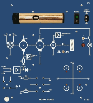
- Can be combined with PID BOARD and MOTOR BOARD
Application and system concept
With the POWER BOARD, hps SystemTechnik provides a demonstration and training system for experiments covering the entire field of power electronics. The board is connected to a single-phase mains supply while the required three-phase AC voltage is generated internally.
The system is designed so that all experiments are carried out at 12 V safety extra-low voltage. This makes the board suitable both for introductory training and for more advanced laboratory work in power electronics.
Functional blocks and measurement options
The POWER BOARD combines uncontrolled and controlled rectifiers, phase-angle control units, burst firing control, pulse-width modulation and an H-bridge with power MOS-FETs in one compact unit.
All important measurement points are available on sockets. Galvanically isolated firing-pulse outputs via firing transformers and bridgeable shunts in the load-current branches enable reproducible earth-free measurements.
Combinations and accessories
The temperature and brightness controlled system Type 5125.5 is included in the scope of delivery. In addition, the POWER BOARD can be combined with the PID BOARD and the MOTOR BOARD for four-quadrant drive experiments and control tasks.
The documentation recommends experiment manual Type V 0121 “Introduction to Power Electronics” as well as accessory set Type 5125.1 with connecting leads and plugs.
- Phase-angle control II with input for a negative setpoint
- Galvanically isolated firing pulse outputs via firing transformers
- Bridgeable shunts for current measurement in the load-current branches
- Phase-angle control I with measurement points available on sockets for single- and multi-pulse operation
- PWM control for investigating smoothing at variable fundamental frequency
- Adapter field for 4 mm to 2 mm transitions and BNC adapters
- Mains voltage
- 230 V AC / 115 V AC (110 V AC), 50...60 Hz, 80 VA
- Mains switch
- ON / OFF with indicator light
- DC supply
- +/- 15 V DC; 2.5 A
- AC supply (L1)
- 12 V AC; 1 A
- Signal generator
- f = 2...100 Hz (for sine-modulated PWM)
- Three-phase source
- Switchable for M3 or B6 circuit, UA eff = 12 V DC
- Galvanic isolation
- All power supplies galvanically isolated from each other
- Controllers
- Phase-angle control I, II and III; burst firing control; pulse-width modulation; switching logic for circulating-current-free four-quadrant drive; GTO pulse shaper
- Rectifiers
- Uncontrolled rectifiers; controlled rectifiers (thyristors); H-bridge (power MOS-FET)
- Additional semiconductors
- 1 x diode, transistor, GTO thyristor, TRIAC
- Resistive load
- 27 Ohm
- Inductive load
- 20 mH
- Capacitive load
- 47 µF
- Temperature actual value
- PTC resistor
- Light actual value
- LDR resistor
- Heating and light source
- Incandescent lamp 12 V / 5 W
- Front panel
- 5 mm laminated material, matt blue, white engraving
- Dimensions (board)
- 532 x 297 x 130 mm (W x H x D)
- Weight (board)
- approx. 5.4 kg
- Dimensions (box version)
- 585 x 425 x 155 mm (with Type 5125.20)
- Weight (box version)
- approx. 8.8 kg
- Dimensions (control module 5125.5)
- 37 x 56 x 35 mm (W x D x H), without connector
- Weight (control module 5125.5)
- approx. 65 g
- Recommended accessories
- Experiment manual Type V 0121 “Introduction to Power Electronics”; accessory set Type 5125.1 (connecting leads and plugs)
- AC mains: Uncontrolled half-wave rectifier
- AC mains: Uncontrolled bridge rectifier
- AC mains: Half-controlled bridge rectifier
- AC mains: Fully controlled bridge rectifier
- AC mains: Line-commutated inverter
- AC mains: Two fully controlled bridge rectifiers anti-parallel with circulating-current-free circuit and optical indication via 2 LEDs
- AC mains: Burst firing control (cycle control)
- DC mains: Basic pulse-width modulation (PWM) circuits
- DC mains: PWM with H-bridge, DC-modulated
- DC mains: PWM with H-bridge, sine-modulated
- GTO (Gate-Turn-Off): Firing pulse conditioning for the GTO
- GTO (Gate-Turn-Off): GTO as a DC chopper
- Three-phase mains: Uncontrolled rectifier (M3)
- Three-phase mains: Uncontrolled rectifier (B6)
- Three-phase mains: Controlled rectifier (M3)
- Three-phase mains: Controlled rectifier (B6)
- Control module 5125.5: Temperature control via PTC resistor with incandescent lamp (12 V / 5 W) as heat source
- Control module 5125.5: Light control via LDR resistor with incandescent lamp as light source
Type numbers and variants of this device as named in the hps manuals. As of 2026-09-06
Taken from the tables of contents of the hps experiment manuals (titles, numbers and pages). All manuals are German; titles are shown in the original language. All manuals and experiments
V 0121 Einführung in die Leistungselektronik Manual · 170 pages 21 experiments
Main device of this manual – applies to all experiments Named in the manual as 5125.5 View table of contents
- 2.1 Die ungesteuerte Einpuls-Mittelpunktschaltung M1U p. 4
- 2.2 Die ungesteuerte Zweipuls-Brückenschaltung B2U p. 9
- 2.3 Die ungesteuerte Dreipuls-Mittelpunktschaltung M3U p. 13
- 2.4 Die ungesteuerte Sechspuls-Brückenschaltung B6U p. 17
- 2.5 Arithmetischer Mittelwert und Effektivwert bei ungesteuerten Gleichrichtern p. 20
- 2.6 Pulszahl und Welligkeit bei ungesteuerten Gleichrichtern p. 23
- 3.1 Die gesteuerte Einpuls-Mittelpunktschaltung M1C p. 26
- 3.2 Die gesteuerte Zweipuls-Brückenschaltung B2C p. 34
- 3.3 Die Phasenanschnitt-Steuerschaltung p. 38
- 3.4 Die halbgesteuerte Zweipuls-Brückenschaltung B2H p. 41
- 3.5 Die gesteuerte Dreipuls-Mittelpunktschaltung M3C p. 46
- 3.6 Wechselrichterbetrieb der gesteuerten Dreipuls-Mittelpunktschaltung M3C mentioned p. 53
- 3.7 Die gesteuerte Sechspuls-Brückenschaltung B6C p. 58
- 3.8 Arithmetischer Mittelwert und Effektivwert des Stromes bei gesteuerten Gleichrichtern p. 63
- 4.1 Die gesteuerte Einphasen-Wechselwegschaltung W1C p. 66
- 4.2 Die Impulsgruppensteuerung p. 71
- 5.1 Die Pulsweitenmodulation p. 74
- 5.2 Pulsweitenmodulierter Gleichstromsteller mit GTO p. 79
- 5.3 Gleichspannungswandler p. 83
- 5.4 MOSFET-H-Brücke mit versetzter Pulsweitenmodulation p. 94
- 6.1 Die H-Brücke als Wechselrichter p. 111
No experiment matches the filter.
V 0124 Versuche zur Leistungselektronik Manual · 163 pages 33 experiments
Main device of this manual – applies to all experiments View table of contents
- Ströme und Spannungen in der ungesteuerten Einpuls-Mittelpunktschaltung M1U bei ohmscher Last p. 1
- Ströme und Spannungen in der ungesteuerten Einpuls-Mittelpunktschaltung M1U bei ohmsch-induktiver Last p. 3
- Ströme und Spannungen in der ungesteuerten Zweipuls-Brückenschaltung B2U bei ohmscher Last p. 5
- Ströme und Spannungen in der ungesteuerten Zweipuls-Brückenschaltung B2U bei ohmsch-induktiver Last p. 7
- Ströme und Spannungen in der ungesteuerten DreipulsmittelPunktschaltung M3U bei ohmscher Last p. 9
- Ströme und Spannungen in der ungesteuerten Sechspuls Mittelpunktschaltung B6U bei ohmscher Last p. 11
- Arithmetischer Mittelwert und Effektivwert, Auswahl geeigneter Messgeräte p. 13
- Pulszahl und Welligkeit bei ungesteuerten Gleichrichtern p. 15
- Signalverläufe einer Phasenanschnittsteuerung p. 17
- Ströme und Spannungen in der gesteuerten Einpuls-Mittelpunktschaltung M1C bei ohmscher Last p. 19
- Einfluss einer induktiven Komponente auf die M1C-Schaltung p. 21
- Ströme und Spannungen der gesteuerten ZweipulsBrückenschaltung B2C bei ohmscher Last p. 23
- Einfluss einer induktiven Komponente auf die B2C-Schaltung p. 25
- Ströme und Spannungen der halbgesteuerten Zweipuls-Brückenschaltung B2HZ p. 27
- Ströme und Spannungen in der gesteuerten Dreipuls-Mittelpunktschaltung M3C p. 29
- Ströme und Spannungen in der gesteuerten Sechspuls-Brückenschaltung B6C p. 31
- Signalverläufe am Diac (Diac als bidirektionaler Schalter) p. 33
- Signalverläufe am Triac mit Phasenanschnittsteuerung W1C p. 35
- Ansteuerung eines Triac mit Hilfe einer Zweirichtungsdiode (Diac) p. 37
- Spannungsverläufe der Impulsgruppensteuerung p. 39
- Erzeugung eines arithmetischen Mittelwertes mit Hilfe eines PWM-Signals und einem Tiefpassfilter p. 3
- Gleichstromsteller Vom 1-Quadrantbetrieb zum 4-Quandrantbetrieb p. 7
- Ansteuer- und Ausgangssignale einer 2-Quadrantenbrücke p. 9
- Ansteuer- und Ausgangssignale einer 4-Quadrantenbrücke (H-Brücke) p. 11
- Einfluss unterschiedlicher PWM Frequenzen am Ausgang einer 2-Quadrantbrücke p. 13
- Linearität einer H-Brücke p. 15
- Wechselrichter in der 2-Quadrantenbrücke p. 17
- Wechselrichter in der 4-Quadrantenbrücke p. 19
- Einfluss der Taktfrequenz auf die sinusbewertete PWM p. 21
- Einfluss der Steuerfrequenz auf die sinusbewertete PWM p. 23
- Ströme und Spannungen beim Abwärtswandler (Step-Down Converter) p. 1
- Ströme und Spannungen beim Aufwärtswandler (Step-Up Converter) p. 3
- Ströme und Spannungen beim Umkehrwandler (Voltage Inverter Converter) p. 5
No experiment matches the filter.
V 0122 Regelstrecken-Regelkreise Manual · 333 pages 0 experiments
Additional device in this manual View table of contents
No experiment matches the filter.
V 0123 Versuche zum STEPPING BOARD Manual · 75 pages 6 experiments
Additional device in this manual View table of contents
- Versuch 1 Sinusförmige Pulsweitenmodulation mit ohmscher Last p. 36
- Versuch 2 Sinusförmige Pulsweitenmodulation mit induktiver Last p. 38
- Versuch 3 Sinusförmige Pulsweitenmodulation mit Rechteckspannung p. 39
- Versuch 4 Sröme und Brückenspannung der beiden Motorwicklungen p. 40
- Versuch 1 Drehzahl und Drehfrequenz p. 43
- Versuch 2 Maximale Drehzahl und Drehrichtung p. 45
Other sections mentioning this product (2)
No experiment matches the filter.