
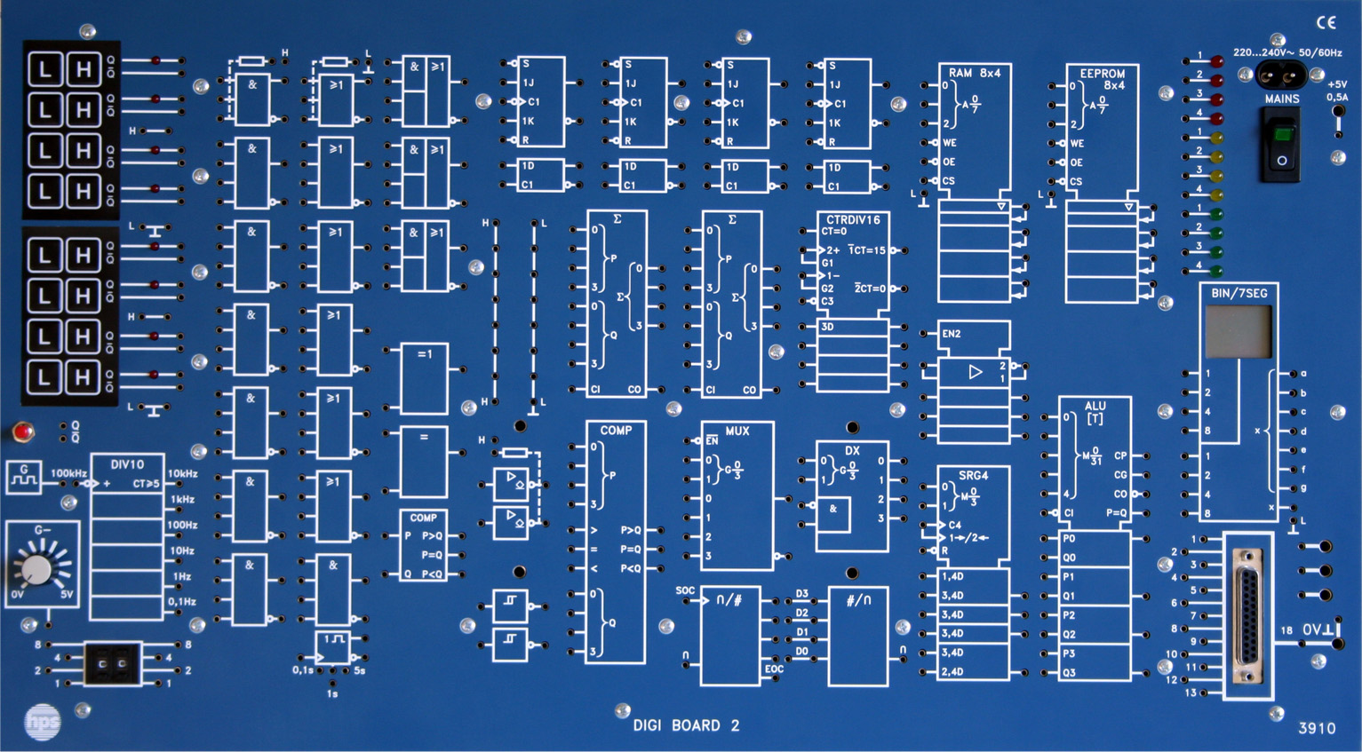
Type 3910
DIGI BOARD 2 Type 3910
The DIGI BOARD 2 Type 3910 is a universal teaching and training unit for the fundamentals of digital and microcomputer technology. All function groups, the power supply, displays and input units are built in so that clear experiments can be assembled directly on the bench.
- Universal teaching and training unit for digital and microcomputer technology
- All function groups and the power supply are built into the unit
- Usable as a table-top unit, demonstration unit or mobile training unit
- Adapter for connection to a computer
- DC signal source 0 ... 5 V / 10 mA
- Integrated digital functions such as gates, flip-flops, counters and ALU
Layout and Functional Groups
The DIGI BOARD 2 introduces digital technology, contactless control engineering and microcomputer technology. The functional groups are wired via 2 mm connection technology.
The unit includes input keypads, a clock generator, hexadecimal/dual code switches, LED displays, 7-segment display, gates, comparators, flip-flops, shift registers, ALU, counters and memory blocks.
Experiment Operation and Accessories
The board can be placed on a table or mounted in a frame stand. In a box it becomes a mobile training unit and can still be used directly for experiments.
The unit comes with the manual 'Experimenting with Digital Technology' Type V 0160 with tasks and solutions covering the standard topics of digital technology.
- Extra modules and expansion slots
- Experiment manual with tasks and solutions
- DC signal source
- 0 ... 5 V / 10 mA
- Internal DC supply
- +5 V / 3 A, short-circuit proof
- External DC supply
- +5 V / 0.5 A, short-circuit proof
- Clock generator
- 100 kHz
- Frequency divider
- 10 kHz, 1 kHz, 100 Hz, 10 Hz, 1 Hz, 0.1 Hz
- Mains supply
- 230 V AC / 115 V AC (110 V AC), 30 VA, 50 ... 60 Hz
- Adapter
- 2 mm sockets to SUB-D 25
- Board version
- 532 x 297 x 95 mm
- Weight board version
- 3.5 kg
- Box version
- 580 x 450 x 155 mm
- Weight box version
- 7.5 kg
- Front panel
- 5 mm laminated press material, matte blue, white engraving
- Additional modules
- 5 V DC / max. 1 A
- Recommended accessories
- V 0160, table frame 8112, accessory set 3910.1, IC BOARD 3530, IC sockets 9156/9156.2/9156.3
- Logic circuits
- Schmitt triggers
- Bistable stages
- Monostable stages
- Code converters and encoders
- Arithmetic circuits
- Counting circuits
- Register circuits
- Multiplex operation
- Arithmetic logic unit
- Memory circuits
- A/D converters
- D/A converters
Taken from the tables of contents of the hps experiment manuals (titles, numbers and pages). All manuals are German; titles are shown in the original language. All manuals and experiments
V 0160 Versuche zur Digitaltechnik Manual · 222 pages 49 experiments
Main device of this manual – applies to all experiments View table of contents
- 1.2.1 Wichtige binäre Verknüpfungen p. 9
- 1.2.2 Gesetze der Schaltalgebra p. 10
- 1.2.3 Disjunktive und konjunktive Normalform p. 15
- 1.2.4 Schaltungsentwurf mit Hilfe von KV-Diagrammen p. 17
- 1.2.5 Darstellung von Schaltnetzen in NAND bzw. NOR-Technik p. 19
- 1.2.6 Äquivalenz p. 22
- 1.2.7 Antivalenz p. 23
- 1.2.8 Arbeiten mit TTL-Bausteinen p. 24
- 2.2 Versuchsteil p. 28
- 3.2.1 RS-Flipflop aus NOR-Gattern p. 33
- 3.2.2 RS-Flipflop aus NAND-Gattern p. 34
- 3.2.3 Taktzustandsgesteuerte RS-Flipflops p. 35
- 3.2.4 RS-Flipflops mit dominierendem S- oder R-Eingang p. 36
- 3.2.5 D-Flipflops p. 37
- 3.2.6 Einflankengesteuertes RS-Flipflop p. 38
- 3.2.7 Zweizustandsgesteuertes D-Flipflop p. 41
- 3.2.8 Einflankengesteuertes JK-Flipflop p. 42
- 4.2.1 Das Monoflop des Digitalen Trainings systems p. 48
- 4.2.2 Verzögerungsschaltungen p. 49
- 5.2.1 8421-BCD / Dezimal-Codeumsetzer p. 56
- 5.2.2 8421-BCD / 7-Segment-Codeumsetzer p. 58
- 5.2.3 Codiererschaltungen p. 61
- 6.2.1 Halbaddierer p. 68
- 6.2.2 Volladdierer p. 70
- 6.2.3 Addierschaltungen für den 8421-BCD-Code p. 72
- 6.2.4 Halbsubtrahierer p. 77
- 6.2.5 Vollsubtrahierer p. 78
- 6.2.6 Subtrahierer für Dualzahlen p. 81
- 6.2.7 2-Bit-Parallel-Multiplikationsschaltung p. 83
- 6.2.8 Rechenwerk für 4-Bit-Dualzahlen p. 85
- 7.2.1 Asynchrone Vorwärtszähler p. 92
- 7.2.2 Asynchrone Rückwärtszähler p. 94
- 7.2.3 Asynchrone Umkehrzähler p. 96
- 7.2.4 Asynchrone Modulo-n-Zähler p. 97
- 7.2.5 Synchronzähler p. 99
- 7.2.6 Programmierbare Zähler p. 102
- 8.2.1 JK-Schieberegister p. 107
- 8.2.2 Schieberegister mit paralleler Dateneingabe p. 109
- 8.2.3 Serielle Datenübertragung p. 111
- 9.2 Versuchsteil p. 117
- 10.2.1 Arithmetische Operationen p. 124
- 10.2.2 ALU mit Akkumulator p. 126
- 11.2.1 Beschreiben und Lesen von Speicher bausteinen p. 132
- 11.2.2 Wortbreite p. 134
- 11.2.3 Speicherkapazität p. 137
- 12.2.1 Analog-Digital-Umsetzung p. 141
- 12.2.2 Digital-Analog-Umsetzung p. 144
- 12.2.3 Signalübertragung p. 146
- 12.2.4 Digitaler Funktionsgenerator p. 148
No experiment matches the filter.
V 0123 Versuche zum STEPPING BOARD Manual · 75 pages 6 experiments
Additional device in this manual View table of contents
- Versuch 2 Zeitkonstante und Einschaltstrom einer Wicklung p. 16
- Versuch 1 Steuerschaltung mit dem DIGI BOARD 2 p. 19
- Versuch 1 Einstrang-Vollschrittbetrieb mit dem DIGI BOARD 2 p. 23
- Versuch 3 Zweistrang-Vollschrittbetrieb mit dem DIGI BOARD 2 p. 25
- Versuch 1 Translator für Rechtslauf mit dem DIGI BOARD 2 p. 27
- Versuch 3 Translator für Rechts- und Linkslauf mit dem DIGI BOARD 2 p. 31
No experiment matches the filter.
V 0174 Grundlagen der Automatisierungstechnik mit SIMATIC STEP 7 Manual · 240 pages 1 experiment
Additional device in this manual View table of contents
- 10.3.1 Projekt „Datenaustausch mit externen Anlagenkomponenten“ p. 234
No experiment matches the filter.
V 0174 Grundlagen der Automatisierungstechnik mit SIMATIC STEP 7 Solutions · 76 pages 1 experiment
Additional device in this manual View table of contents
- 10 Praktische Übungen p. 49
No experiment matches the filter.


