Type 5261
Frequency Converter Type 5261
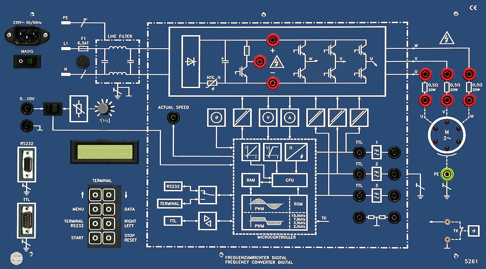
The Frequency Converter Type 5261 is a training system for three-phase induction motors in the 100 W to 1 kW range. It offers four-quadrant operation, extensive protection functions, integrated measurement and indication, and terminal or PC control via RS 232.
- For three-phase induction motors from 100 W to 1 kW
- Four-quadrant operation with integrated control and indication
- Parameter assignment via terminal or PC through RS 232
- Protection against overcurrent, overvoltage, undervoltage, excess temperature, short-circuit and earth fault
- Integrated measurement and display of current, voltage and frequency
- Operation via membrane keyboard, LCD display or software
Application and operating range
With the Frequency Converter, hps SystemTechnik provides a training system for experiments in the field of speed control and speed regulation of three-phase induction motors.
The unit is designed for use with motors from 100 W to 1 kW and supports four-quadrant operation, integrated display functions and control via terminal or external PC.
Software and control
The included DFUwin software supports the U/f diagram, the travel diagram, current and voltage display, brake and start voltage display, and the simultaneous display of all parameters.
The software runs under Windows XP, Vista and Windows 7 in 32-bit and 64-bit editions.
Recommended accessories
The manual "Frequency Converter Digital" (Type V 0022), a three-phase induction motor Type 2707.1, the load Type 5512, the isolation amplifier Type 8630, the universal power supply Type 2740.1, a storage oscilloscope, the PC software 5261 EVGB, the RS 232 connecting lead Type 9102.50, the DC brake unit Type 2718 and the optional USB/RS 232 converter Type 9102.55 are listed as recommended accessories.
DC brake unit Type 2718
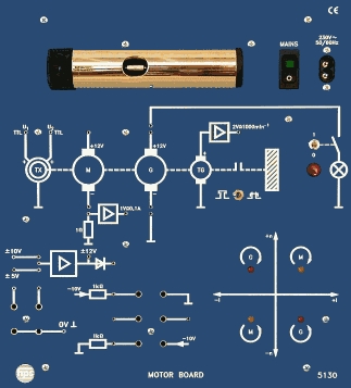
The DC brake unit is intended for use in drive engineering, for example in experiments with a three-phase induction motor and the frequency converter.
It can be used as a motor or as a generator and consists of a shunt-wound DC machine with integrated DC tachogenerator mounted on a base.
The experimental machine is pushed onto the base and held by a single-lever quick-action clamping device; a coupling collar Type 2718.5 is included.
Mechanical design
The front panel of the Frequency Converter is made of 5 mm thick laminate, matte blue in colour and engraved with white symbols representing the built-in function groups.
The additional machine, software screenshots and auxiliary components from the original product presentation are preserved as supporting material for the training system.
- Software for U/f curve, travel diagram and live parameter display
- Expandable with the DC brake unit and additional measuring accessories
- Mains connection (single-phase)
- Voltage 230 V AC +/- 10 %, current consumption max. 6.3 A, mains frequency 48 Hz ... 400 Hz
- Output
- Output voltage 3 x 220 V, 0.5 ... 120 Hz; output current max. 4.5 A; limit frequency 120 Hz (adjustable)
- Braking and acceleration ramp
- 11.5 Hz/s ... 588.1 Hz/s
- Pulse width modulation (PWM)
- Frequencies 2.0 kHz, 3.9 kHz, 7.8 kHz and 15.6 kHz
- Protection functions
- Overvoltage and undervoltage, overcurrent, excess temperature of the power unit, excess temperature of the motor, short-circuit and earth fault
- SUB-D connection (9-pin)
- For control of the frequency converter with TTL level
- Other
- Control unit electrically isolated; braking resistor 150 Ohm / 50 W; inputs for setpoint frequency via built-in potentiometer or external 0 ... 10 V
- Mechanical data
- Front panel made of 5 mm thick laminate, matte blue, with white symbols engraved; dimensions 532 x 297 x 165 mm (W x H x D), weight approx. 6.2 kg
- DC brake unit Type 2718
- Shunt-wound DC machine with armature voltage and current 205 V / 2 A, field voltage and current 205 V / 0.33 A, power 0.3 kW at 2000 rpm, protection through thermal contact; DC tachogenerator with output 1: 10 V at 1500 rpm and output 2: 10 V at 3000 rpm; base material brushed stainless steel, dimensions 710 x 220 x 250 mm (W x H x D), weight 13.7 kg
- 1 Fundamentals1
- 1.1 The three-phase induction motor with squirrel-cage rotor1
- 1.1.1 The structure of the motor1
- 1.1.2 The speed of the rotary field2
- 1.1.3 Torque and slip2
- 1.1.4 Characteristic points3
- 1.1.5 Speed control4
- 1.2 Static converter systems for speed regulation of the three-phase induction motor7
- 1.2.1 General7
- 1.2.2 I-converter7
- 1.2.3 U-converter7
- 1.3 Digital Frequency Converter (Type 5261) from hps10
- 1.3.1 General10
- 1.3.2 Constructional features of the power unit10
- 1.3.3 Function principle of an inverter11
- 1.3.4 Constructional features of the control unit14
- 2 Commissioning and measuring technique21
- 2.1 Operation of the terminal21
- 2.1.1 Parameter, functions and basic settings21
- 2.1.2 Error messages of the Digital Frequency Converter (Type 5261)23
- 2.2 The connection of a three-phase induction motor24
- 2.3 Speed control, clockwise/anticlockwise rotation of a three-phase induction motor25
- 2.4 LED rotating field and measuring points25
- 2.5 Necessary accessories and measuring instruments26
- 2.6 Safety instructions for handling the system27
- 3 The frequency converter software DFUwin29
- 3.1 Software requirements29
- 3.2 Hardware requirements29
- 3.3 Software installation29
- 3.3.1 Installation under Windows 3.1x29
- 3.3.2 Installation under Windows 9529
- 3.4 The U/f diagram30
- 3.5 The travel diagram33
- 4 Experiments with Rs compensation35
- Experiment 1: Max. perm. BOOST of a three-phase induction motor35
- Experiment 2: LED field of rotation36
- Experiment 3: Direction of rotation37
- Experiment 4: Digital control signals of the frequency converter38
- Experiment 5: Maximum deviation40
- Experiment 6: Analog control signals of the frequency converter42
- Experiment 7: U/f characteristic45
- 5 Experiments with the power unit47
- Experiment 1: Intermediate circuit voltage47
- Experiment 2: Effect of the brake chopper48
- 6 Experiments with the frequency control of a three-phase induction motor51
- Experiment 1: Field of rotation speed, idle speed and idle slip51
- Experiment 2: Frequency dependence of the idle current55
- Experiment 3: Motor voltage depending on the PWM frequency57
- Experiment 4: Speed and slip in sin. PWM59
- Experiment 5: Speed and slip in trapez. PWM65
- 7 Experiments with acceleration and braking of a three-phase induction motor71
- Experiment 1: Acceleration of a three-phase induction motor without load71
- Experiment 2: Acceleration of a three-phase induction motor with load75
- Experiment 3: Travel diagram with DFUwin81
- 8 Experiments with the speed control with a three-phase induction motor83
- Experiment 1: Speed control independently of the load83
- Experiment 2: Speed control with setpoint jump86
- 9 The synchronous machine89
- 9.1 Fundamentals89
- 9.1.1 Structure of the machine89
- 9.1.2 Operating behaviour as a motor90
- 9.1.3 Connecting the machine92
- 9.2 Experiments with the synchronous motor93
- Experiment 1: Max. perm. BOOST of a synchronous machine93
- Experiment 2: Acceleration of a synchronous motor without load94
- Experiment 3: Acceleration on load and sinusoidal PWM98
- Experiment 4: Acceleration on load and trapezoidal PWM102
Taken from the tables of contents of the hps experiment manuals (titles, numbers and pages). All manuals are German; titles are shown in the original language. All manuals and experiments
V 0022 Versuche zum Frequenzumrichter Digital Manual · 120 pages 28 experiments
Main device of this manual – applies to all experiments View table of contents
- 3.1 Systemvoraussetzungen p. 25
- 3.2.1 Installation unter Windows 3.1x p. 25
- 3.2.2 Installation unter Windows 95 p. 25
- 3.3 Das U/f-Diagramm p. 26
- 3.4 Das Fahrdiagramm p. 28
- 4.1 Maximal zulässiger BOOST eines DSAM mentioned p. 29
- 4.2 LED-Drehfeld mentioned p. 30
- 4.3 Drehrichtung mentioned p. 31
- 4.4 Digitale Steuersignale des Frequenzumrichters mentioned p. 32
- 4.5 Maximaler Hub mentioned p. 34
- 4.6 Analoge Steuersignale des Frequenzumrichters mentioned p. 36
- 4.7 U/f-Kennlinie mentioned p. 39
- 5.1 Zwischenkreisspannung mentioned p. 41
- 5.2 Wirkung des Brems-Choppers mentioned p. 42
- 6.1 Drehfelddrehzahl, Leerlaufdrehzahl und Leerlaufschlupf mentioned p. 44
- 6.2 Frequenzabhängigkeit des Leerlaufstromes mentioned p. 47
- 6.3 Motorspannung in Abhängigkeit von der PWM-Frequenz mentioned p. 49
- 6.4 Drehzahl und Schlupf bei Sinus-PWM mentioned p. 51
- 6.5 Drehzahl und Schlupf bei Trapez-PWM mentioned p. 56
- 7.1 Beschleunigung eines DSAM ohne Last mentioned p. 61
- 7.2 Beschleunigung eines DSAM bei Last mentioned p. 64
- 7.3 Fahrdiagramm mit DFUwin mentioned p. 68
- 8.1 Drehzahlregelung unabhängig von der Belastung mentioned p. 70
- 8.2 Drehzahlregelung mit Sollwertsprung mentioned p. 73
- 9.2.1 Maximal zulässiger BOOST einer Synchronmaschine mentioned p. 79
- 9.2.2 Beschleunigung eines Synchronmotors ohne Last mentioned p. 80
- 9.2.3 Beschleunigung bei Last und Sinus-PWM mentioned p. 83
- 9.2.4 Beschleunigung bei Last und Trapez-PWM mentioned p. 86
Other sections mentioning this product (4)
- 1.3 Der Frequenzumrichter Digital (Typ 5261) p. 10
- 1.3.3 Funktionsprinzip eines Wechselrichters p. 11
- 2.1.2 Fehlermeldungen des Frequenzumrichters Digital (Typ 5261) p. 20
- 2.4 LED-Drehfeld und Messpunkte p. 22
No experiment matches the filter.