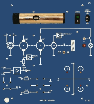
Type 5255
Type 5255 Four-Quadrant Drive
The Type 5255 Four-Quadrant Drive is a teaching and learning unit for speed control and speed regulation of DC shunt-wound machines. It supports circulating-current and non-circulating-current operation, includes built-in current and speed controllers, and can be combined with a separate DC brake unit.
- Compact construction with short setup times
- Suitable for DC machines from 100 W to 1 kW
- Circulating-current and non-circulating-current operation switchable
- Built-in controllers for current and speed
- Optical indication of thyristor switching states
- Test jacks for electrical parameters
Purpose and principle
With the Four-Quadrant Drive, hps SystemTechnik offers a teaching and learning unit for experiments in the field of speed control and speed regulation of DC shunt-wound machines.
Provision is made for recording and displaying all important electrical parameters. Detailed experiment instructions are available for the experiments.
The Four-Quadrant Drive is designed for DC machines up to 1 kW. It can be placed on the desk or mounted in a frame rack.
- Teaching and learning unit for speed control and speed regulation
- Suitable for DC shunt-wound machines
- Desk or frame-rack operation
- Separate experiment instructions available
DC brake unit and accessories
The DC brake unit is intended for use in drive technology, for example for experiments with a DC shunt-wound machine and the Four-Quadrant Drive. It can be used as a motor and also as a generator.
It consists of a DC shunt-wound machine with integrated DC tachogenerator mounted on a base. The base also serves for mounting and mechanically connecting test machines.
- Experiment manual Type V 0015
- DC shunt-wound machine Type 2701 or DC compound machine Type 2704
- Universal power supply Type 2740.1
- Load Type 5512, three filament lamps and one switch
- Measuring devices: oscilloscope with probe, isolation amplifier, multimeter and speed indicator
- DC brake unit Type 2718
- Usable as a desk unit or in a frame rack
- Mains voltage
- 230 V AC; 50 ... 60 Hz
- Power consumption
- approx. 200 VA ... 1.1 kVA, depending on the connected machine set
- Armature voltage and current
- max. 207 V; 6 A
- Field voltage and current
- max. 207 V; 2.5 A
- Speed controller
- Proportional action factor KP continuously adjustable; integral action in 3 stages
- Temperature monitoring
- For motor set, via 2 mm sockets
- Base material
- Stainless steel, brushed
- Dimensions
- 532 x 297 x 190 mm (W x H x D)
- Weight
- approx. 14.9 kg
- DC brake unit armature voltage and current
- 205 V / 2 A
- DC brake unit field voltage and current
- 205 V / 0.33 A
- DC brake unit power
- 0.3 kW at 2000 rpm
- DC brake unit tachogenerator
- 10 V at 1500 rpm and 10 V at 3000 rpm
- DC brake unit dimensions
- 710 x 220 x 250 mm (W x H x D)
- DC brake unit weight
- 13.7 kg
- ContentsI
- 1 Fundamental Principles1
- 1.1 The shunt-wound DC machine1
- 1.1.1 Structure of the machine1
- 1.1.2 Operating behaviour as a motor1
- 1.1.3 Operating behaviour as a generator2
- 1.1.3.1 The externally excited shunt-wound generator2
- 1.1.3.2 The self-excited shunt-wound generator2
- 1.1.4 Starting up the machine2
- 1.1.5 Connecting the machine3
- 1.2 Current converter systems for adjusting the speed of DC machines4
- 1.2.1 General information4
- 1.2.2 The uncontrolled rectifier4
- 1.2.2.1 The uncontrolled double-pulse bridge circuit B2U4
- 1.2.2.2 The uncontrolled six-pulse bridge circuit B6U5
- 1.2.3 The controlled rectifier6
- 1.2.3.1 The controlled single-pulse mid-point circuit M1C6
- 1.2.3.2 The controlled double-pulse bridge circuit B2C8
- 1.2.3.3 The controlled six-pulse bridge circuit B6C10
- 1.2.4 Inverter stability12
- 1.2.5 Current converter drives with DC machines in four-quadrant operation12
- 1.2.6 Current converter drives without circuit current13
- 1.2.7 Current converter drives with circuit current13
- 1.3 The Four Quadrant Drive (Type 5255) from hps14
- 1.3.1 General14
- 1.3.2 The power unit14
- 1.3.3 The firing components15
- 1.3.4 The block-up logic15
- 1.3.5 The speed controller15
- 1.3.6 The current controllers 1 and 216
- 1.3.7 The release signal16
- 1.3.8 Generation of the field voltage16
- 2 Introduction for Conducting the Experiments17
- 2.1 Auxiliary equipment required from hps SystemTechnik17
- 2.1.1 DC Brake Unit (Type 2718)17
- 2.1.2 Universal Power Supply (Type 2740.1)17
- 2.1.3 Shunt-Wound DC Machine (Type 2701)17
- 2.1.4 Isolation Amplifier (Type 8630)18
- 2.1.5 Load (Type 5512)18
- 2.1.6 Speed Indicator (Type 5511.1)18
- 2.2 Safety instructions18
- 2.2.1 General safety instructions18
- 2.2.2 Safety instructions for the Four Quadrant Drive (Type 5255)18
- 2.2.3 Safety instructions for the DC Brake Unit (Type 2718) and the Shunt-Wound DC Machine (Type 2701)18
- 2.2.4 Safety instructions for the Universal Power Supply (Type 2740.1)19
- 2.2.5 Safety instructions for the Isolation Amplifier (Type 8630)19
- 2.3 Putting into operation19
- 2.3.1 General19
- 2.3.2 Setting the currents Imax1 and Imax2 of the Four Quadrant Drive (Type 5255)20
- 2.3.3 Offset adjustment for the speed controller of the Four Quadrant Drive (Type 5255)21
- 2.3.4 Setting the maximum speed nmax. of the Four Quadrant Drive (Type 5255)21
- 3 Experiments with the Four-Quadrant Drive (Type 5255)23
- 3.1 Determining the field voltage23
- 3.2 Determining the synchronization signal25
- 3.3 Determining the firing pulses in operation without circuit current27
- 3.4 Determining the firing pulses in operation with circuit current31
- 3.5 Speed characteristic of the tachogenerator35
- 3.6 Voltage and current curves with ohmic loading of a thyristor bridge38
- 3.7 Mean value of armature voltage and speed with ohmic inductive loading in operation without circuit current43
- 3.8 Mean value of armature voltage and speed with ohmic inductive loading in operation with circuit current47
- 3.9 Maximum motor speeds in operation without circuit current at different controller settings51
- 3.10 Maximum motor speeds in operation with circuit current at different controller settings54
- 3.11 Behaviour at speed jumps with load and different controller settings57
- 3.12 Transition from motor to generator mode61
- 3.13 Transition from motor to generator mode with change in the direction of rotation64
- 4 Solutions section
- 4.1 Solutions to chapter 2.3.2S1
- 4.2 Solutions to chapter 3.1S2
- 4.3 Solutions to chapter 3.2S3
- 4.4 Solutions to chapter 3.3S4
- 4.5 Solutions to chapter 3.4S7
- 4.6 Solutions to chapter 3.5S10
- 4.7 Solutions to chapter 3.6S11
- 4.8 Solutions to chapter 3.7S19
- 4.9 Solutions to chapter 3.8S21
- 4.10 Solutions to chapter 3.9S23
- 4.11 Solutions to chapter 3.10S24
- 4.12 Solutions to chapter 3.11S25
- 4.13 Solutions to chapter 3.12S29
- 4.14 Solutions to chapter 3.13S30
- 5 AppendixA1
- 5.1 Abbreviations and formula symbolsA1
- 5.3 Correlation matrixA2
- OverheadsO1
Taken from the tables of contents of the hps experiment manuals (titles, numbers and pages). All manuals are German; titles are shown in the original language. All manuals and experiments
V 0015 Versuche zum Vierquadrant-Antrieb Manual · 105 pages 13 experiments
Main device of this manual – applies to all experiments View table of contents
- 3.1 Ermittlung der Feldspannung mentioned p. 23
- 3.2 Ermittlung des Synchronisiersignals mentioned p. 25
- 3.3 Ermittlung der Zündimpulse im kreisstromfreien Betrieb mentioned p. 27
- 3.4 Ermittlung der Zündimpulse im kreisstrombehafteten Betrieb mentioned p. 31
- 3.5 Drehzahlkennlinie des Tachogenerators mentioned p. 35
- 3.6 Spannungs- und Stromverlauf bei ohmscher Belastung einer Thyristorbrücke mentioned p. 38
- 3.7 Mittelwert von Ankerspannung und Drehzahl bei ohmsch-induktiver Belastung im kreis stromfreien Betrieb mentioned p. 43
- 3.8 Mittelwert von Ankerspannung und Drehzahl bei ohmsch-induktiver Belastung im kreis strombehafteten Betrieb mentioned p. 47
- 3.9 Maximale Motordrehzahlen im kreisstromfreien Betrieb bei unterschiedlichen Reglerein stellungen mentioned p. 51
- 3.10 Maximale Motordrehzahlen im kreisstrombehafteten Betrieb bei unterschiedlichen Regler einstellungen mentioned p. 54
- 3.11 Verhalten bei Drehzahlsprüngen mit Belastung und unterschiedlichen Reglereinstellungen mentioned p. 57
- 3.12 Übergang vom Motor- zum Generatorbetrieb mentioned p. 61
- 3.13 Übergang vom Motor- zum Generatorbetrieb mit Drehrichtungsänderung mentioned p. 64
Other sections mentioning this product (9)
- 1.1.4 Das Anlassen der Maschine p. 2
- 1.2.2.1 Die ungesteuerte Zweipuls-Brückenschaltung B2U p. 4
- 1.2.5 Stromrichterantriebe mit Gleichstrommaschinen im Vierquadrant-Betrieb p. 12
- 1.3.2 Das Leistungsteil p. 14
- 1.3.5 Der Drehzahlregler p. 15
- 1.3.8 Die Erzeugung der Feldspannung p. 16
- 2.3.1 Allgemeine Hinweise p. 19
- 2.3.2 Einstellung der Ströme Imax. 1 und Imax. 2 des Vierquadrant-Antriebs (Typ 5255) p. 20
- 2.3.4 Einstellung der maximalen Drehzahl nmax. des Vierquadrant-Antriebs (Typ 5255) p. 21
No experiment matches the filter.