Type 5255 Four – Quadrant Drive
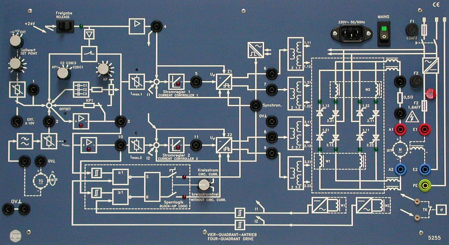
- Compact construction for fast setup
- For machine sets of 100 W … 1 kW
- Circulating current and circulating current-free operation, switchable
- Built-in controllers for current and speed
- Optical indicator for thyristor switching states
- Test jacks for recording electrical parameters
![]() – Data sheet
– Data sheet
![]() – Experiment manuals, contents
– Experiment manuals, contents

