
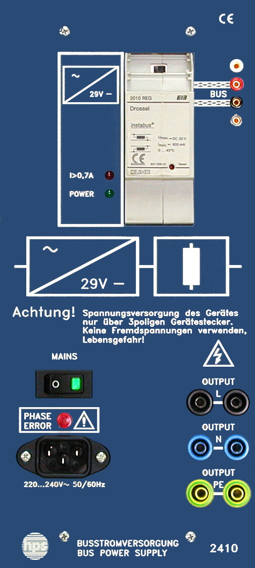
Type 2410
EIB / KNX Demo Panels Series 2410
The EIB / KNX Demo Panels Series 2410 is a modular training system for installation technology. The panels can be used on a desk, in a demonstration frame, or as a mobile teaching unit and are powered from a single-phase outlet.
- Modular training system for the European Installation Bus (EIB / KNX)
- Suitable as a desktop unit, in a demonstration frame, or in the PC lab
- A single-phase mains socket is sufficient for power supply
- Inputs and outputs wired via 4 mm safety sockets
- Bus continuity realised via 2 mm sockets
- UP bus couplers and components mounted separately for direct access to the programming button
Application and system concept
The EIB / KNX demo panels form a modular training system for practical exercises in building and installation technology.
The panels can be used in a suitable inclined position on a desk, in a demonstration frame, or as a mobile training unit. A single-phase mains socket is sufficient for operation.
Wiring and operation
Inputs and outputs are wired via 4 mm safety sockets. Bus continuity is provided via 2 mm sockets so that the interconnections remain easy to follow during training.
UP bus couplers and the associated EIB / KNX components are mounted separately so the programming button remains directly accessible at all times.
Accessories and expansion
The system is designed to work with safety leads, a USB connection lead, and ETS software. The didactic manual V 0118-V4 "KNX House and Building Systems Technology" is provided as a companion document.
The EXTENSION BOARD allows additional EIB / KNX components to be mounted on a DIN rail and integrated into the training setup.
Mechanical design
The front panel is made of 5 mm laminated material; the rear side is a plastic sloped cover.
An integrated bus detector indicates bus activity and supports troubleshooting during the experiments.
- Integrated bus detector for bus activity display
- Expandable with the EXTENSION BOARD for DIN-rail mounting
- Conventional installation technology can be integrated
- Didactically prepared manual V 0118-V4 available
- Mechanical data
- Front panel made of 5 mm laminated material; rear side as a plastic sloped cover.
- Bus power supply (Type 2410)
- Mains input 230 V AC, 50 ... 60 Hz, 50 VA; mains output 230 V / 3 A; internal fuse 3.15 A; bus voltage 29 V DC / 640 mA with built-in choke; additional voltage tap via 2 mm sockets; LEDs for readiness and overload; 133 x 297 x 110 mm; approx. 0.9 kg.
- Data interface (Type 2411)
- RS 232 for programming the system from a PC together with ETS; UP bus coupler mounted separately; 133 x 297 x 125 mm; approx. 0.6 kg.
- 4-channel switching actuator (Type 2412)
- For switching four individual loads; supply voltage 230 V AC; rated voltage and current 230 V AC / 6 A; 133 x 297 x 110 mm; approx. 0.8 kg.
- 6-channel consumer module (Type 2413)
- Six lamps E1 ... E6; rated voltage 230 V AC; power consumption approx. 5 W per lamp; 133 x 297 x 100 mm; approx. 0.8 kg.
- 4-channel push-button sensor (Type 2414)
- Four programmable key pairs with LEDs; UP bus coupler mounted separately; 133 x 297 x 105 mm; approx. 0.6 kg.
- 4-channel binary input (Type 2415)
- Converts 230 V AC switching signals into bus signals; conventional installation technology can be integrated; 133 x 297 x 110 mm; approx. 0.7 kg.
- Switch / push-button (Type 2416)
- Four ON / OFF switches (Q1 ... Q4) with pilot lamp and two push-buttons (S1 / S2); rated voltage 230 V AC; 133 x 297 x 100 mm; approx. 0.7 kg.
- Info display (Type 2417)
- Visualises 16 freely configurable bus messages; up to 5 lines with 30 characters each; 133 x 297 x 100 mm; approx. 0.5 kg.
- Room temperature controller (Type 2419)
- For a realistic heating control loop; setpoint can be adjusted from approx. -4 °C ... +45 °C; operating status indicated by 5 LEDs; 133 x 297 x 100 mm; approx. 0.5 kg.
- Line / area coupler (Type 2420)
- For creating a subordinate line; also usable as area coupler and repeater; integrated choke; 133 x 297 x 110 mm; approx. 0.7 kg.
- Motion detector (Type 2421)
- Outputs a bus telegram when it detects a moving object; 133 x 297 x 110 mm; approx. 0.5 kg.
- Combined sensor (Type 2422)
- Converts temperature and brightness into bus telegrams; 133 x 297 x 130 mm; approx. 0.5 kg.
- Blind actuator, 2-channel (Type 2423)
- For setting up blind control with two blinds; 133 x 297 x 110 mm; approx. 0.7 kg.
- Dimmer actuator (Type 2424)
- Universal dimmer actuator for controlling electrical loads; 133 x 297 x 110 mm; approx. 0.7 kg.
- Blind (Type 2425)
- Blind for connection to the blind actuator; upper and lower end positions limited by integrated end switches.
- Actuator (Type 2426)
- Demonstration model of a radiator valve actuator; recommended for use with the room temperature controller.
- IR receiver (Type 2427)
- Programmable push-button with built-in IR receiver and UP bus coupler; 133 x 297 x 125 mm; approx. 0.6 kg.
- USB data interface (Type 2429)
- USB interface for programming the system from a PC together with ETS3; 133 x 297 x 125 mm; approx. 0.6 kg.
- 1 Technology of the European Installation Bus System (EIB / KNX)1
- 1.1 Scope of application of EIB / KNX1
- 1.2 Topology2
- 1.3 Power supply and cable lengths4
- 1.4 Communication within the EIB system4
- 1.4.1 Transmission technology4
- 1.4.2 Bus participants4
- 1.4.3 Bus access method5
- 1.4.4 Telegram structure6
- 1.4.5 Transmission time9
- 1.4.6 Byte structure within a telegram9
- 1.5 EIB / KNX components used in the manual10
- 1.5.1 Push-button sensor10
- 1.5.2 Bus coupler10
- 1.5.3 Chokes10
- 1.5.4 Data interface10
- 1.5.5 Binary inputs10
- 1.5.6 Binary outputs11
- 2 The Engineering Tool Software ETS3 Professional13
- 2.1 System requirements13
- 2.2 Software installation13
- 2.2.1 Installation under Windows 3.1x14
- 2.2.2 Installation under Windows 95, 98, ME, 2000, NT, XP, ...14
- 2.3 Working with ETS3 Professional14
- 2.4 Starting and exiting ETS3Pro14
- 2.5 ETS3Pro standard view16
- 2.6 Popup menus15 ... 16
- 3 Safety notes for handling the system17
- 4 Experiments on switching off19
- 4.1 Switching off with a switch19
- 4.2 Switching off with switch and push-button28
- 4.3 Switching off with 4-way push-button sensor29
- 4.4 Switching off with central off, push-button and 4-way push-button sensor30
- 5 Experiments on two-way switching33
- 5.1 Two-way switching with two switches33
- 5.2 Two-way switching with two switches and double push-button35
- 5.3 Two-way switching with 4-way push-button sensor and double push-button36
- 5.4 Two-way switching with 4-way push-button sensor and double push-button36
- 6 Experiments on cross and impulse relay switching37
- 6.1 Cross switching37
- 6.2 Impulse relay switching39
- 7 Experiments on brightness control41
- 7.1 Simulation of a twilight switch41
- 7.2 Simulation of a twilight switch41
- 8 Testing and fault diagnosis of EIB / KNX projects43
- 8.1 Check physical addresses43
- 8.2 Query device information44
- 8.3 Read the bus device memory45
- 8.4 Diagnose group addresses45
- 8.5 Record EIB / KNX telegrams47


