
Type 2330
SAFETY BOARD Type 2330
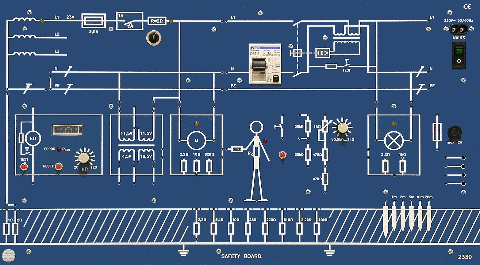
The SAFETY BOARD Type 2330 is a compact training system for electrical safety measures according to VDE 0100. All experiments are carried out with protective extra-low voltage, require only a single-phase mains outlet and can be performed without any special room installation.
- Combines all important safety measures according to VDE 0100 in one board
- Integrated power supply, connection to a single-phase mains outlet is sufficient
- Protective extra-low voltage for especially safe experimentation
- Integrated experiment components for short setup and reset times
- TT, TN-C-S and IT network configurations selectable by rewiring
- LED indication for visual status monitoring of key functional groups
Application and Safety Concept
With the SAFETY BOARD, hps SystemTechnik provides a training system that is ideally suited for experiments in the field of electrical safety measures.
The unit can be used in any room without special installation because all experiments are carried out with protective extra-low voltage and the device requires only a single-phase mains supply.
Integrated Experiment Environment
The operational status of the most important assemblies is indicated visually by LEDs.
To minimize setup and reset time, all required experiment components have been integrated directly into the SAFETY BOARD.
The compact design of this training system makes it possible to store even several units in a very small space.
Experiment Manual and Topics
hps SystemTechnik offers the manual "Electrical Safety Engineering" for the SAFETY BOARD with task and solution sections. The corresponding table of contents / experiment manual is linked on the product page as a separate PDF.
Setup, Demonstration and Transport
For experiments, the SAFETY BOARD is placed on the table at an ergonomic angle or suspended in an hps frame for demonstration purposes.
The SAFETY BOARD can also be screwed into a box. The box is used for secure transport and storage of the SAFETY BOARD.
All experiments can also be carried out directly inside the box.
Mechanical Design
The front panel of the SAFETY BOARD is made of 5 mm laminated press material in matte blue and is engraved with white circuit symbols corresponding to the integrated functional groups.
A sturdy plastic cover protects the rear side of the unit and, due to its shape, provides an ergonomic inclined position on the table.
- Detailed experiment manuals with tasks and solutions available
- Board can be placed on a desk at an ergonomic angle or mounted in an hps frame
- Optional box operation for transport, storage and direct experimentation
- Compact construction allows several units to be stored in minimal space
- Mains connection
- 230 V AC / 115 V AC (110 V AC), 50 ... 60 Hz, 40 VA; L1' = 23 V, 1.5 A for safe experimentation
- RCD circuit breaker
- Single-phase, with test button, IF = 30 mA
- Insulation monitor
- With test and reset button, adjustable earth resistance 20 kOhm ... 120 kOhm
- Human symbol
- With pluggable body resistance of 2.4 kOhm and 820 Ohm
- Fuse
- Freely usable up to 2 A, switchable via 2 mm sockets
- Motor load
- Body faults can be simulated via switchable resistances of 2.2 Ohm, 10 Ohm and 820 Ohm
- Lamp load
- Body faults can be simulated via switchable resistances of 2.2 Ohm and 1 kOhm
- Transformer
- Usable as extra-low-voltage transformer, autotransformer, isolating transformer and summation current transformer
- Earth electrode / auxiliary electrode
- With measuring points for potential funnel measurement at 1 / 2 / 5 / 10 / 20 m
- Board dimensions
- 532 x 297 x 110 mm (W x H x D)
- Board weight
- approx. 4.5 kg
- Box dimensions
- 580 x 450 x 155 mm
- Total weight with box
- approx. 7.25 kg
- Recommended accessories
- Experiment manual Electrical Safety Engineering Type V 0119; accessory set Type 2330.1 with connecting leads and 2 mm plugs
- Protection against direct and indirect contact: Direct contact
- Protection against direct and indirect contact: Indirect contact and suitable protective measures
- Protective extra-low voltage: Touch voltage UB and fault current IB
- Autotransformer: Hazards of the autotransformer
- Overcurrent protective devices: Overcurrent protection in TN-C systems
- Overcurrent protective devices: Overcurrent protection in TT systems
- Summation current transformer: Currents through the summation current transformer
- Residual-current device: FI circuit breaker (RCD)
- Protective measures in TN systems: Earth fault of one outer conductor
- Protective measures in TN systems: Determination of loop impedance ZS
- Protective measures in TN systems: Faults in TN systems
- Protective measures in TT systems: Checking the RCD
- Protective measures in TT systems: RCD tripping behavior depending on earth and fault resistance
- Measurement of earth resistance: Earthing via earth resistance RA
- Measurement of earth resistance: Direct earthing via rod electrode
- Protective measures in IT systems: IT system with one fault
- Protective measures in IT systems: IT system with two faults
- Protective insulation: Insulation fault
- Protective separation: Single, double and multiple faults
- Earth electrode: Potential funnel and step voltage US
Taken from the tables of contents of the hps experiment manuals (titles, numbers and pages). All manuals are German; titles are shown in the original language. All manuals and experiments
V 0119 Elektrische Schutztechnik Manual · 97 pages 20 experiments
Main device of this manual – applies to all experiments View table of contents
- 2.2.1 Direktes Berühren p. 14
- 2.2.2 Indirektes Berühren und geeignete Schutzmaßnahmen p. 16
- 3.2.1 Berührungsspannung UB und Fehlerstrom IB p. 22
- 4.2.1 Gefahren des Spartransformators p. 26
- 5.2.1 Überstrom-Schutzeinrichtungen im TN-C-System p. 32
- 5.2.2 Überstrom-Schutzeinrichtungen im TT-System p. 34
- 6.2.1 Ströme durch den Summenstromwandler p. 38
- 7.2.1 RCD (FI-Schutzschalter) p. 45
- 8.2.1 Erdschluss eines Außenleiters p. 54
- 8.2.2 Bestimmung der Schleifenimpedanz ZS p. 57
- 8.2.3 Fehler im TN-System p. 61
- 9.2.1 Überprüfung des RCDs p. 64
- 9.2.2 Auslöseverhalten des RCDs in Abhängigkeit vom Erdungs- und Fehlerwiderstand p. 66
- 10.2.1 Erdung über Erdungswiderstand RA p. 70
- 10.2.2 Direkte Erdung über Staberder p. 72
- 11.2.1 IT-System mit einem Fehler p. 76
- 11.2.2 IT-System mit zwei Fehlern p. 78
- 12.2.1 Isolationsfehler p. 83
- 13.2.1 Einfach-, Doppel- und Mehrfachfehler p. 86
- 14.2.1 Spannungstrichter und Schrittspannung US p. 91
No experiment matches the filter.
V 0119 Elektrische Schutztechnik Solutions · 24 pages 20 experiments
Main device of this manual – applies to all experiments View table of contents
- 2.2.1 Direktes Berühren p. 5
- 2.2.2 Indirektes Berühren und geeignete Schutzmaßnahmen p. 5
- 3.2.1 Berührungsspannung UB und Fehlerstrom IB p. 9
- 4.2.1 Gefahren des Spartransformators p. 11
- 5.2.1 Überstrom-Schutzeinrichtungen im TN-C-System p. 13
- 5.2.2 Überstrom-Schutzeinrichtungen im TT-System p. 13
- 6.2.1 Ströme durch den Summenstromwandler p. 15
- 7.2.1 FI-Schutzschalter (RCD) p. 17
- 8.2.1 Erdschluss eines Außenleiters p. 19
- 8.2.2 Bestimmung der Schleifenimpedanz ZS p. 20
- 8.2.3 Fehler im TN-System p. 22
- 9.2.1 Überprüfung des RCDs p. 23
- 9.2.2 Auslöseverhalten des RCDs in Abhängigkeit vom Erdungs- und Fehlerwiderstand p. 23
- 10.2.1 Erdung über Erdungswiderstand RA p. 25
- 10.2.2 Direkte Erdung über Staberder p. 25
- 11.2.1 IT-System mit einem Fehler p. 27
- 11.2.2 IT-System mit zwei Fehlern p. 27
- 12.2.1 Isolationsfehler p. 29
- 13.2.1 Einfach-, Doppel- und Mehrfachfehler p. 31
- 14.2.1 Spannungstrichter und Schrittspannung US p. 33
No experiment matches the filter.


