
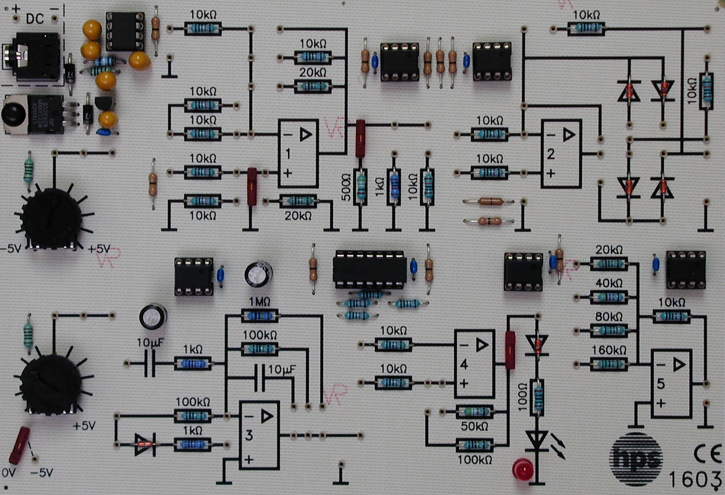
Type 1603
OPLAB Type 1603
The OPLAB Type 1603 is a compact LABLine system for analogue circuit training with operational amplifiers. All components and supply sources are arranged so that working OP circuits can be built quickly with only a few jumpers and patch leads.
- Compact training system for analogue circuit techniques with operational amplifiers
- All components and voltage sources clearly arranged on one board
- Five operational amplifiers for the most common OP circuits
- OP1 for inverting and non-inverting amplifiers with variable resistor configuration
- OP2 for rectifier circuits
- OP3 for integrator and differentiator circuits
Practical operational amplifier training
The OPLAB is designed as a multi-purpose platform for experiments in analogue circuit techniques. All components and supply sources are placed so that working circuits can be built quickly using only a few jumpers and connecting leads.
This makes the board suitable for structured classroom and laboratory work on the setup and investigation of typical operational amplifier circuits.
Five OP stages on one board
Five operational amplifiers are available for the most common circuit types: inverting and non-inverting amplifiers, rectifier circuits, integrators, differentiators, comparators with and without hysteresis, and a digital-to-analogue converter.
Several OP stages can also be interconnected, for example to build a sawtooth generator.
Signal sources and workbook
The required input signals for the OP circuits are provided either by two adjustable voltage sources integrated on the board or by the hps measuring interface Type 1620.
An accompanying workbook covers the main fundamentals and applications of operational amplifier technology, from basic circuits to generator and converter functions.
- OP4 for comparator circuits with and without hysteresis
- OP5 for digital-to-analogue conversion
- Several OP stages can be combined for more complex circuits such as a sawtooth generator
- Two integrated adjustable voltage sources provide input signals directly on the board
- Can be extended with the hps measuring interface Type 1620
- Workbook with many OP topics available
- Supply voltage
- 12 V DC via supplied plug-in power supply
- Internal supply
- +/- 7 V
- Board dimensions
- 190 x 130 mm
- Operational amplifier functions
- OP1 inverting / non-inverting amplifier; OP2 rectifier circuits; OP3 integrator / differentiator; OP4 comparator with and without hysteresis; OP5 D/A converter
- Signal generation
- Two integrated adjustable voltage sources or hps measuring interface Type 1620
- Recommended measuring equipment
- Simple multimeter; hps measuring interface Type 1620
- Theoretical introduction to operational amplifier technology
- Inverting basic circuit
- Non-inverting amplifier
- Impedance converter
- Adder circuit
- Subtractor circuit
- Differential amplifier
- Comparator
- Schmitt trigger
- Precision rectifier
- Integrator
- Triangle and sawtooth generator
- Differentiator
- Digital / analogue converter
Taken from the tables of contents of the hps experiment manuals (titles, numbers and pages). All manuals are German; titles are shown in the original language. All manuals and experiments
V 1653 OPLab Manual · 72 pages 36 experiments
Main device of this manual – applies to all experiments View table of contents
- 1.3 Bauformen p. 2
- 1.4 Kenndaten p. 3
- 2.2.1 Der invertierende Gleichspannungsverstärker p. 7
- 2.2.2 Der invertierende Gleichspannungsverstärker p. 8
- 2.2.3 Der invertierende Wechselspannungsverstärker p. 11
- 3.2.1 Der nichtinvertierende Gleichspannungsverstärker p. 14
- 3.2.2 Der nichtinvertierende Gleichspannungsverstärker p. 15
- 3.2.3 Der nichtinvertierende Wechselspannungsverstärker p. 17
- 4.2.1 Untersuchung eines Impedanzwandlers p. 20
- 5.2.1 Untersuchung eines Summierers p. 22
- 5.2.2 Untersuchung eines Summierers p. 23
- 5.2.3 Untersuchung eines verstärkenden Summierers p. 24
- 5.2.4 Untersuchung eines verstärkenden Summierers p. 25
- 5.2.5 Addition von Gleich- und Wechselspannungen p. 26
- 6.2.1 Untersuchung eines Subtrahieres p. 28
- 6.2.2 Untersuchung eines Subtrahieres p. 29
- 7.2.1 Untersuchung eines Differenzspannungsverstärkers p. 31
- 7.2.2 Untersuchung eines Differenzspannungsverstärkers p. 32
- 8.2.1 Untersuchung eines Komparators p. 34
- 8.2.2 Untersuchung eines Komparators p. 35
- 9.2.1 Messung der Umschaltpunkte eines Schmitt-Triggers p. 37
- 9.2.2 Die Hysteresekennlinie eines Operationsverstärkers p. 40
- 9.2.3 Die Verschiebung der Schaltschwellen beim Schmitt-Trigger p. 41
- 10.2.1 Die einfache Einweg-Gleichrichtung mit Diode p. 43
- 10.2.2 Untersuchung eines Einweg-Präzisionsgleichrichters p. 44
- 10.2.3 Untersuchung eines Zweiweg-Präzisionsgleichrichters p. 46
- 11.2.1 Integration einer Rechteckspannung p. 48
- 11.2.2 Integration einer Sinusspannung p. 50
- 12.2.1 Untersuchung des Dreieckgenerators p. 53
- 12.2.2 Untersuchung des Sägezahngenerators p. 54
- 13.2.1 Differenziation einer Dreieckspannung p. 56
- 13.2.2 Differenziation einer Sinusspannung p. 57
- 13.2.3 Differenziation einer Rechteckspannung p. 58
- 14.2.1 Untersuchung eines D/A-Wandlers p. 61
- 15.2.1 Untersuchung des Frequenzverhaltens eines Tiefpassfilters p. 65
- 15.2.2 Untersuchung eines Tiefpassfilters bei Rechteckspannung p. 67
No experiment matches the filter.
V 1653 OPLab Solutions · 26 pages 0 experiments
Main device of this manual – applies to all experiments View table of contents
No experiment matches the filter.


