Type 8630
Isolation Amplifier Type 8630
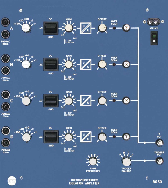
Type 8630 enables galvanically isolated, floating measurement of up to four signals with an oscilloscope. It is suitable for basic experiments through to power electronics and can be used as a bench unit or in a demonstration frame.
- 4 floating differential inputs
- Each input switchable to GND, DC or AC
- Selectable low-pass filter
- Fully isolated BNC sockets on all measurement outputs
- Overload indication for all channels
- Galvanic isolation with only 0.008 percent linearity error
Application
The isolation amplifier was designed for floating and safe measurement of different voltages in combination with an oscilloscope. Up to four signals with different reference points can be displayed on one oscilloscope channel.
Operation and mechanics
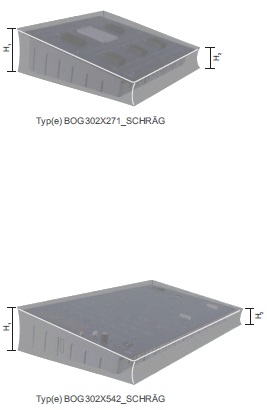
The front panel is made of 5 mm laminated press material in matte blue. The rear side is protected by a grey plastic housing that also allows the unit to stand at an inclined angle on the desk.
- Coupling capacitance of only 2 pF
- For bench use or demonstration frame use
- Mains connection
- 230 V AC, 50 ... 60 Hz, 20 VA; 110 V on request
- Differential inputs
- 4, floating and galvanically isolated from each other
- Inputs
- 4 fully isolated BNC sockets or multiplex mode via one fully isolated BNC socket
- Frequency range
- approx. 2 kHz ... 50 kHz
- Low-pass filter
- 500 Hz
- Input resistance
- 1 MOhm
- Input capacitance
- 30 pF
- Cut-off frequency
- 50 kHz (-3 dB)
- Output voltage
- < -8 V, > +8 V
- Zero-position adjuster
- +/-8 V
- Dimensions
- 266 x 297 x 110 mm (W x H x D)
- Weight
- approx. 2.4 kg
Taken from the tables of contents of the hps experiment manuals (titles, numbers and pages). All manuals are German; titles are shown in the original language. All manuals and experiments
V 0015 Versuche zum Vierquadrant-Antrieb Manual · 105 pages 9 experiments
Additional device in this manual View table of contents
- 3.2 Ermittlung des Synchronisiersignals p. 25
- 3.3 Ermittlung der Zündimpulse im kreisstromfreien Betrieb p. 27
- 3.4 Ermittlung der Zündimpulse im kreisstrombehafteten Betrieb p. 31
- 3.6 Spannungs- und Stromverlauf bei ohmscher Belastung einer Thyristorbrücke p. 38
- 3.7 Mittelwert von Ankerspannung und Drehzahl bei ohmsch-induktiver Belastung im kreis stromfreien Betrieb p. 43
- 3.8 Mittelwert von Ankerspannung und Drehzahl bei ohmsch-induktiver Belastung im kreis strombehafteten Betrieb p. 47
- 3.11 Verhalten bei Drehzahlsprüngen mit Belastung und unterschiedlichen Reglereinstellungen p. 57
- 3.12 Übergang vom Motor- zum Generatorbetrieb p. 61
- 3.13 Übergang vom Motor- zum Generatorbetrieb mit Drehrichtungsänderung p. 64
Other sections mentioning this product (2)
- 2.1.4 Trennverstärker (Typ 8630) p. 17
- 2.3.1 Allgemeine Hinweise p. 19
No experiment matches the filter.
V 0022 Versuche zum Frequenzumrichter Digital Manual · 120 pages 8 experiments
Additional device in this manual View table of contents
- 4.6 Analoge Steuersignale des Frequenzumrichters p. 36
- 5.2 Wirkung des Brems-Choppers p. 42
- 6.3 Motorspannung in Abhängigkeit von der PWM-Frequenz p. 49
- 7.1 Beschleunigung eines DSAM ohne Last p. 61
- 7.2 Beschleunigung eines DSAM bei Last p. 64
- 9.2.2 Beschleunigung eines Synchronmotors ohne Last p. 80
- 9.2.3 Beschleunigung bei Last und Sinus-PWM p. 83
- 9.2.4 Beschleunigung bei Last und Trapez-PWM p. 86
No experiment matches the filter.