
Type 3840
SENSORICS BOARD Type 3840
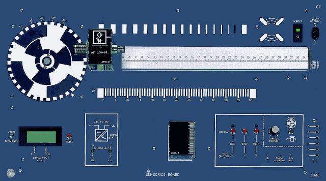
The SENSORICS BOARD Type 3840 is a training system for sensorics and automation technology with integrated power supply, counter and frequency meter. It conveys the design, principles and application of industrial sensors in practical experiments.
- Training and instruction system for sensorics and automation technology
- Built-in power supply with integrated counter and frequency meter
- Rotary and linear motion with motors for realistic experiments
- Can be controlled by PLC, PC, TTL signals or manually
- Clear storage of accessories on a separate board
- Expandable with ultrasonic, fibre optic, analog and NAMUR sensors
Training Concept
The SENSORICS BOARD provides a training concept that explains the principles, construction and application of industrial sensors through practical experiments.
It is well suited as an introduction for machine builders, mechanics and technicians in control, production and hybrid systems. The selected sensors reflect common market use in control and automation technology.
- Standard sensor set: inductive sensor, capacitive sensor, optical sensor and magnetic field sensor
- Options: ultrasonic sensor, fibre optic sensor, NAMUR sensors and analog sensor
Experiment Setup and Mechanics
All parts required for experiments are integrated into the SENSORICS BOARD for fast and clear setup.
Sensors are inserted into a movable carriage that can also be controlled directly. A millimetre scale on the guide rail supports positioning tasks and evaluation.
A motor-driven rotating disc can also be sensed. Both motors are protected by electronic current shut-off.
All accessories are arranged on a separate storage panel. The board can be used on a desk, in a rack or in a box; the box supports secure transport, storage and direct experimentation when opened.
- Also available in a box version for transport, storage and direct use
- Mains voltage
- 230 V AC / 115 V AC (110 V AC)
- Mains frequency
- 50 ... 60 Hz
- Power consumption
- 40 VA
- Integrated sensor supply
- 24 V DC / 250 mA, short-circuit protected output
- Indicators
- LED indicators, U: approx. 15 V ... 30 V
- Start-stop logic
- With optical indicators, clockwise and counter-clockwise operation for rotating disc or carriage
- Control inputs
- For PLC or TTL operation, U: approx. 5 V ... 24 V
- Analog input
- 0 ... 10 V, R = approx. 100 kOhm, switchable ext./int. for carriage motor control
- Frequency range
- 1 ... 9999 Hz
- Frequency meter input level
- 5 ... 24 V
- Pulse counter
- 1 ... 9999
- Board dimensions
- 532 x 297 x 120 mm (W x H x D)
- Accessory set dimensions
- 532 x 297 x 120 mm (W x H x D)
- Box dimensions
- 570 x 450 x 150 mm (W x H x D)
- Board weight
- approx. 3.7 kg
- Accessory set weight
- approx. 2.4 kg
- Box version weight
- approx. 10.5 kg
- Included accessories
- Accessory set Type 3840.10 with storage panel, sensors, material samples and connecting leads
- Sensorics: Response curve
- Sensorics: Switching hysteresis
- Sensorics: Switching distance and switching behaviour
- Sensorics: Material dependency and reduction factors
- Sensorics: Pulse counting and speed measurement
- Sensorics: Triggering through a housing wall
- Sensorics: Level detection
- Sensorics: Resolution and sensing range of optical sensors
- Sensorics: Applications of fibre optics
- Sensorics: Position detection and control of a transport carriage
- Sensorics: Tool positioning
- Sensorics: Detection of registration marks
Taken from the tables of contents of the hps experiment manuals (titles, numbers and pages). All manuals are German; titles are shown in the original language. All manuals and experiments
V 0140 Sensortechnik – Bausteine der Automatisierungstechnik Manual · 166 pages 40 experiments
Main device of this manual – applies to all experiments View table of contents
- 2.2.1 Ansprechkurve des induktiven Sensors p. 19
- 2.2.2 Schalthysterese p. 24
- 2.2.3 Schaltverhalten Materialabhängigkeit p. 24
- 2.2.4 Reduktionsfaktor p. 25
- 2.2.5 Auslösen eines Schaltvorganges durch eine Gehäusewand p. 26
- 2.2.6 Frequenz-/Drehzahlmessung p. 28
- 2.2.7 Oszillatorfrequenz p. 31
- 3.2.1 Ansprechkurve p. 35
- 3.2.2 Betätigungsvarianten p. 37
- 3.2.3 Schaltverhalten Materialabhängigkeit p. 38
- 3.2.4 Reduktionsfaktor p. 39
- 3.2.5 Auslösen eines Schaltvorganges durch eine Gehäusewand und Prüfen von Wandstärken p. 40
- 3.2.6 Füllstandserfassung p. 41
- 3.2.7 Frequenz-/Drehzahlmessung p. 42
- 4.2.1 Ansprechkurve p. 47
- 4.2.2 Schaltabstand p. 49
- 4.2.3 Schalthysterese p. 50
- 4.2.4 Schaltverhalten Materialabhängigkeit p. 51
- 4.2.5 Auslösen eines Schaltvorganges durch eine Gehäusewand p. 52
- 5.2.1 Frequenz-/Drehzahlmessung p. 56
- 5.2.2 Schaltverhalten p. 57
- 5.2.3 Tastweite/Abstandshysterese p. 59
- 6.2.1 Materialabhängigkeit p. 61
- 6.2.2 Oszillatorfrequenz p. 63
- 7.2.1 Auslösen eines Schaltvorganges durch ein Objekt im Erfassungsbereich p. 72
- 7.2.2 Laufzeitmessung p. 72
- 7.2.3 Ansprechkurve p. 74
- 7.2.4 Ermittlung der maximal zulässigen Geschwindigkeit p. 76
- 8.2.1 Strom-Weg-Kennlinie des induktiven NAMUR-Sensors p. 80
- 8.2.2 Überprüfung der Schaltpunkte beim induktiven NAMUR-Sensor p. 82
- 8.2.3 Leitungsbruch- und Kurzschlussüberwachung beim induktiven NAMUR-Sensor p. 83
- 8.2.4 Oszillatorfrequenz des induktiven NAMUR-Sensors p. 85
- 8.2.5 Strom-Weg-Kennlinie des kapazitiven NAMUR-Sensors p. 86
- 8.2.6 Strom-Weg-Kennlinie des NAMUR-Magnetfeldsensors p. 88
- 8.2.7 Ansprechkurven des NAMUR-Magnetfeldsensors bei einem bewegten Dauermagneten p. 90
- 9.2.1 Erfassungsbereich p. 94
- 9.2.2 Frequenz-/Drehzahlmessung p. 96
- 9.2.3 Erfassung von Strichmarkierungen p. 97
- 9.2.4 Erfassung von relativen Positionen p. 98
- 9.2.5 Durchmesser p. 99
Other sections mentioning this product (1)
- 1.2.2 Aufsetzen des Materialprobenhalters p. 11
No experiment matches the filter.
V 0141 Versuche IO-Link Sensoren Manual · 122 pages 70 experiments
Main device of this manual – applies to all experiments View table of contents
- 1.1 Was ist IO-Link p. 1
- 1.2 Aus welchen Komponeten besteht IO-Link p. 1
- 1.3 IO-Link-Schnittstelle p. 3
- 1.4 IO-Link-Protokoll p. 4
- 1.5 Geräteprofile p. 5
- 1.6 IODD und Engineering p. 6
- 1.7 Unterschiede IO-Link-Spezifikation V1.0 und V1.1 p. 7
- 1.8 Ändern und Sichern von Geräteeinstellungen im laufenden Betrieb p. 7
- 1.9 Tausch eines Devices bzw. Masters im Betrieb p. 8
- 1.1 Einsatz und Anwendung von Induktiven Sensoren I-1
- 1.4 Kennenlernen des induktiven IO-Link Sensors (im Hauptfenster des Sensors) I-4
- 1.5 Shortcut Funktionen im Hauptfenster des Sensors I-5
- 1.6 Hinweis Änderungen und Daten im Sensor abspeichern I-5
- Versuch 1 Schaltabstand bei SP1 Naher Schaltabstand I-6
- Versuch 2 Schaltabstand SP2 Sn I-8
- Versuch 3 Fensterbetrieb und Schaltpunktlogik I-10
- Versuch 4 Stabilitätsalarm I-12
- Versuch 4.1 Stabilitätsalarm Schaltpunktbetrieb I-12
- Versuch 4.2 Stabilitätsalarm im Fensterbetrieb / Anzeige der Prozessdaten I-14
- Versuch 5 Impulsverlängerung I-14 Versuche zum opto-elektronischen IO-Link Distanzsensor O-1 bis O-12
- 1.1 Einsatz und Anwendung von Distanzsensoren O-1
- 1.4.1 Weitere Erklärungen im Hauptfenster des Sensors O-6
- 1.5 Hinweis Änderungen und Daten im Sensor abspeichern O-7
- Versuch 1 Ermittlung des Messbereiches eines Distanzsensors O-8
- Versuch 2 Schaltpunkt und Hysterese im Single Point Mode ermitteln O-9
- Versuch 3 Schaltpunkt des Sensors im Window Betrieb ermitteln O-11 Versuche zum Ultraschall IO-Link Sensor U-1 bis U-22
- 1.1 Einsatz und Anwendung von Ultraschallsensoren U-1
- 1.4 Kennenlernen des Ultraschall IO-Link Sensors im Hauptfenster des Sensors U-4
- 1.5 Shortcut Funktionen im Hauptfenster des Sensors U-6
- 1.6 Hinweis Änderungen und Daten im Sensor abspeichern U-7
- Versuch 1 Fensterbetrieb U-8
- Versuch 2 Schaltpunktbetrieb und Untersuchung der Schallkeulenbreite U-10
- Versuch 2.1 Schaltpunktbetrieb U-10
- Versuch 2.2 Untersuchung der Schallkeulenbreite (im Schaltpunktbetrieb) U-12
- Versuch 3 Hysteresebetrieb U-14
- Versuch 3.1 Hysteresebetrieb U-14
- Versuch 3.2 Hysteresebetrieb mit Einschaltverzug. U-17
- Versuch 4 Reflexschrankenbetrieb U-18 Versuche zum IO-Link Positionsmesssystem P-1 bis P-16
- 1.1 Einsatz und Anwendung von Positionsmesssystemenen. P-1
- 1.4 Kennenlernen des Positionssensors im Hauptfenster des Sensors P-4
- 1.5 Shortcut Funktionen im Hauptfenster des Sensors P-5
- 1.6 Hinweis Änderungen und Daten im Sensor abspeichern P-6
- Versuch 1 Schaltpunktmodus Einpunktbetrieb am Schaltsignal 1 P-7
- Versuch 2 Schaltpunktmodus im Fensterbetrieb (normal / zentriert) P-9 Versuch 2a: Schaltpunktmodus im Fensterbetrieb am Schaltsignal 2 normal P-9 Versuch 2b: Schaltpunktmodus im zentrierten Fensterbetrieb am Schaltsignal 2 P-11
- Versuch 3 Schaltpunktmodus Zweipunktbetrieb am Schaltsignal 2 P-13
- Versuch 4 Übung zum Analogausgang P-15
- Versuch 5 Aktuellen Sensor in einer Anlage finden und lokalisieren P-16 Lösungsteil IO-Link Sensoren V0141 DE Lösungsteil zum induktiven IO-Link Sensor I-L1 bis I-L4
- Versuch 1 Schaltabstand bei SP1 Naher Schaltabstand I-L1
- Versuch 2 Schaltabstand SP2 Sn I-L2
- Versuch 3 Fensterbetrieb und Schaltpunktlogik I-L3
- Versuch 4 Stabilitätsalarm I-L4
- Versuch 4.1 Stabilitätsalarm Schaltpunktbetrieb I-L4
- Versuch 4.2 Stabilitätsalarm im Fensterbetrieb / Anzeige der Prozessdaten I-L4
- Versuch 5 Impulsverlängerung I-L4 Lösungsteil zum opto-elektronischen IO-Link Distanzsensor O-L1 bis O-L2
- Versuch 1 Ermittlung des Messbereiches eines Distanzsensors O-L1
- Versuch 2 Schaltpunkt und Hysterese im Single Point Mode ermitteln O-L1
- Versuch 3 Schaltpunkt des Sensors im Window Betrieb ermitteln O-L2 Lösungsteil zum Ultraschall IO-Link Sensor U-L1 bis U-L8
- Versuch 1 Fensterbetrieb U-L1
- Versuch 2 Schaltpunktbetrieb und Untersuchung der Schallkeulenbreite U-L2
- Versuch 2.1 Schaltpunktbetrieb U-L2
- Versuch 2.2 Untersuchung der Schallkeulenbreite (im Schaltpunktbetrieb) U-L3
- Versuch 3 Hysteresebetrieb U-L4
- Versuch 3.1 Hysteresebetrieb U-L4
- Versuch 3.2 Hysteresebetrieb mit Einschaltverzug. U-L5
- Versuch 4 Reflexschrankenbetrieb U-L6 Lösungsteil zum IO-Link Positionsmesssystem P-L1 bis P-L4
- Versuch 1 Schaltpunktmodus Einpunktbetrieb am Schaltsignal 1 P-L1
- Versuch 2 Schaltpunktmodus im Fensterbetrieb (normal / zentriert) P-L2 Versuch 2a: Schaltpunktmodus im Fensterbetrieb am Schaltsignal 2 normal P-L2 Versuch 2b: Schaltpunktmodus im zentrierten Fensterbetrieb am Schaltsignal 2 P-L2
- Versuch 3 Schaltpunktmodus Zweipunktbetrieb am Schaltsignal 2 P-L3
- Versuch 4 Übung zum Analogausgang P-L3
- Versuch 5 Aktuellen Sensor in einer Anlage finden und lokalisieren P-L4 Anhang V00141 DE Installations- und Benutzeranweisung Pepperl+Fuchs S1 bis S14
No experiment matches the filter.


