
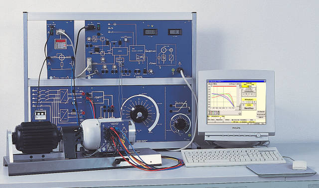
Type 2700
Electrical Machines Series 2700
The Electrical Machines Series 2700 is a training system for plotting characteristics of DC, AC and three-phase machines. With brake unit, universal power supply, universal resistor and PC connection, machine characteristics can be recorded manually or with software support.
- Training system for plotting characteristics of electrical machines, manually and with a PC
- Quick-clamping device for test machines with frame heights of 63 mm, 71 mm and 80 mm
- Existing machines with one shaft end can also be used
- Braking and driving of the test machines is wear-free via the brake unit
- Universal Power Meter with digital display and RS-232 interface
- Universal power supply with fixed and adjustable DC plus AC and three-phase AC
System concept
With the Electrical Machines training system, hps SystemTechnik provides a modern programme for plotting characteristics of DC, AC and three-phase machines.
The system consists of a control unit, brake unit, universal power supply, universal resistor, electrical machines, Universal Power Meter and the interface for electrical machines with software.
Operation and setup
The control unit, universal power supply and universal resistor can be placed directly on the bench with a slight incline or hung into an hps bench or demonstration frame.
The front panels are wired with 4 mm safety sockets; the rear sides are protected by a grey metal housing.
PC connection and evaluation
Speed and torque values are prepared for the PC via the USB interface. In combination with the Universal Power Meter, additional values such as voltage, current and power can be supplied to the PC.
The AC Machines / DC Machines software enables load control, characteristic-curve acquisition and tabular as well as graphical display of the measured values.
- Universal resistor usable as starting resistor, load resistor and field rheostat
- PC connection for characteristics and measured-value acquisition
- Control unit Type 2730
- Frequency converter, control unit, speed display and torque display; operating range 0.5 ... 120 Hz in both directions; mains input 220 ... 230 V AC, 50 ... 60 Hz; dimensions 532 x 297 x 185 mm; weight approx. 7.5 kg; accessories: 4-pole, 8-pole and 2 mm connection leads.
- Brake unit Type 2719
- Suspended three-phase induction machine with parallel bending beam and full DMS bridge, 2-channel encoder and quick-clamping device; speed range about 15 ... 3600 rpm in both directions; power 450 W at 50 Hz and 750 W at 87 Hz; dimensions 680 x 220 x 240 mm; weight 15.1 kg.
- Universal power supply Type 2740.1
- Three-phase mains input 380 ... 415 V AC; three-phase outputs with phase indicator lamps and 3-pole protective switch 6 A; fixed DC approx. 200 V / 4 A, adjustable DC 0 ... 250 V / 4 A; dimensions 266 x 297 x 195 mm; weight approx. 8.6 kg.
- Universal resistor Type 2750
- 500 W ring resistor with protective series resistor, 5-step winding, series resistor and integrated bridge rectifier; 100 W ring resistor as field rheostat; dimensions 532 x 297 x 210 mm; weight approx. 7.7 kg.
- Electrical machines of series 2700
- Terminal boards printed with the appropriate symbols, 4 mm safety sockets (2 mm for thermal contacts), colour light grey RAL 7035, all machines mounted on four feet and fitted with one coupling half; the range includes DC shunt motor 2701, DC series motor 2702, DC compound motor 2703, DC compound machine 2704, universal motor 2705, repulsion motor 2706, three-phase induction motors 2707 and 2707.1, slip-ring rotor 2708, multifunction machine 2708.1, Dahlander motor 2709, three-phase induction motor with separate windings 2710, synchronous machine 2711, auxiliary-phase motor 2712, capacitor motor 2715 and shaded-pole motor 2716.
- Section models
- Section models for 2701, 2707.1, 2708 and 2711; additional variants available on request; all cut surfaces are protected with clear varnish.
- Machine feet
- Set of 4 pieces for height and width adaptation; Type 2720.1 height 12 mm for 80 mm frame height, Type 2720.2 height 21 mm for 71 mm frame height, Type 2720.3 height 29 mm for 63 mm frame height; diameter 45 mm.
- Coupling half Type 2720.4
- Mounted on the shaft with an Allen screw; standard bore 8.1 mm, available from 8.1 ... 15.9 mm; length 30 mm, diameter 36.5 mm; material sintered iron.
- USB INTERFACE
- 25-pin D-sub device socket for connection to the control unit Type 2730, USB connection to the PC, mains input 220 ... 240 V AC; dimensions 133 x 297 x 110 mm; approx. 1.4 kg; PC requirements: IBM-compatible PC with Windows 2000/XP/Vista/7, free USB and serial port.
- Recommended accessories
- Multimeter, phase angle meter, UNIVERSAL POWER METER Type 1091, safety leads and connectors, manual V 0170.
- 1 Facts about electrical machines1
- 1.1 Electrical machines in general1
- 1.2 Standardised designs1
- 1.3 Construction1
- 1.4 Cooling and ventilation1
- 1.5 Insulation classes2
- 1.6 Motors and their operating behaviour2
- 1.7 Direction of rotation2
- 1.8 Operating mode as a motor selection criterion3
- 1.9 Degree of protection as a safety factor4
- 1.10 The nameplate as user information5
- 1.11 Connection designations6
- 1.12 Efficiency and losses6
- 2 Important notes on commissioning the system7
- 2.1 Safety instructions for handling the system7
- 2.2 Use of a motor protection switch8
- 2.3 Characteristic-curve acquisition with an XY recorder9
- 2.4 The torque attenuator of the control unit9
- 3 Three-phase induction motor with squirrel-cage rotor11
- 3.1 Construction of the motor11
- 3.2 Synchronous speed12
- 3.3 Torque and slip12
- 3.4 Operating behaviour13
- 3.5 Motor connection13
- 3.6 Star-delta starting14
- 3.7 Operation on single-phase mains15
- 3.8 Experiments with squirrel-cage rotor induction motor16
- 4 Dahlander motor25
- 4.1 Construction of the motor25
- 4.2 Operating behaviour25
- 4.3 Motor connection26
- 4.4 Experiments with the Dahlander motor27
- 5 Three-phase induction motor with separate windings37
- 5.1 Construction of the motor37
- 5.2 Operating behaviour37
- 5.3 Motor connection38
- 5.4 Experiments with the three-phase induction motor with separate windings39
- 6 Slip-ring rotor49
- 6.1 Construction of the motor49
- 6.2 Operating behaviour49
- 6.3 Motor connection50
- 6.4 Experiments with the slip-ring rotor51
- 7 Capacitor motor59
- 7.1 Construction of the motor59
- 7.2 Operating behaviour60
- 7.3 Motor connection60
- 7.4 Experiments with the capacitor motor61
- 8 Synchronous machine71
- 8.1 Construction of the machine71
- 8.1.1 External pole machine71
- 8.1.2 Internal pole machine71
- 8.1.3 Damper winding72
- 8.2 Excitation types for synchronous generators72
- 8.3 Operating behaviour as a generator73
- 8.4 Synchronisation in generator operation74
- 8.5 Operation of the synchronous machine as a motor75
- 8.5.1 Operating behaviour as a motor75
- 8.5.2 Overexcitation of the synchronous motor75
- 8.5.3 Synchronous motor as a phase shifter76
- 8.5.4 Speed control of the synchronous motor76
- 8.6 Motor connection76
- 8.7 Experiments with the synchronous generator77
- 8.8 Experiments with the synchronous motor86
- 9 Facts about DC machines95
- 9.1 Construction95
- 9.2 Function of the commutator96
- 9.3 Operating behaviour96
- 9.4 Fields of the DC machine96
- 9.5 Starting methods for DC machines98
- 9.6 Speed control of DC machines98
- 9.7 Reversal of rotation direction for DC machines99
- 9.8 Types of DC machines99
- 9.9 Connection designations for DC machines100
- 9.10 Braking methods for DC machines100
- 10 DC shunt machine101
- 10.1 Construction of the machine101
- 10.2 Operating behaviour as a motor101
- 10.3 Operating behaviour as a generator102
- 10.4 Starting the machine103
- 10.5 Motor connection103
- 10.6 Experiments with the DC shunt motor104
- 10.7 Experiments with the DC shunt generator115
- 11 DC series machine123
- 11.1 Construction of the machine123
- 11.2 Operating behaviour as a motor123
- 11.3 Operating behaviour as a generator123
- 11.4 Starting the machine124
- 11.5 Motor connection124
- 11.6 Experiments with the DC series motor125
- 11.7 Experiments with the DC series generator131
- 12 DC compound machine135
- 12.1 Construction of the machine135
- 12.2 Operating behaviour as a motor135
- 12.3 Operating behaviour as a generator136
- 12.4 Starting the machine136
- 12.5 Motor connection136
- 12.6 Experiments with the DC compound motor137
- 13 DC compound machine149
- 13.1 Construction of the machine149
- 13.2 Operating behaviour as a motor149
- 13.3 Operating behaviour as a generator150
- 13.4 Starting the machine150
- 13.5 Motor connection150
- 13.6 Experiments with the DC compound motor151
- 13.7 Experiments with the DC compound generator162
- 14 Universal motor173
- 14.1 Construction of the motor173
- 14.2 Operating behaviour173
- 14.3 Motor connection174
- 14.4 Experiments with the universal motor175
Type numbers and variants of this device as named in the hps manuals. As of 2026-09-06
| Type | Description | Experiments | Manuals |
|---|---|---|---|
| 2701 | No description in the manual | 22 | V 0015 V 0170 |
| 2702 | No description in the manual | 5 | V 0170 |
| 2703 | No description in the manual | 6 | V 0170 |
| 2704 | No description in the manual | 7 | V 0170 |
| 2705 | No description in the manual | 4 | V 0170 |
| 2707 | No description in the manual | 5 | V 0170 |
| 2708 | No description in the manual | 3 | V 0170 |
| 2709 | No description in the manual | 4 | V 0170 |
| 2710 | No description in the manual | 4 | V 0170 |
| 2711 | No description in the manual | 14 | V 0022 V 0170 |
| 2715 | No description in the manual | 4 | V 0170 |
| 2718 | No description in the manual | 26 | V 0015 V 0022 |
| 2719 | No description in the manual | 42 | V 0170 |
| 2730 | No description in the manual | 42 | V 0170 |
| 2737 | No description in the manual | V 0170 | |
| 2750 | No description in the manual | 11 | V 0170 |
| 2707.1 | No description in the manual | 18 | V 0022 |
| 2719.1 | No description in the manual | 2 | V 0015 V 0022 V 0170 |
| 2737.4 | No description in the manual | V 0170 | |
| 2740.1 | No description in the manual | 53 | V 0015 V 0022 V 0170 |
Taken from the tables of contents of the hps experiment manuals (titles, numbers and pages). All manuals are German; titles are shown in the original language. All manuals and experiments
V 0170 Elektrische Maschinen Manual · 206 pages 89 experiments
Main device of this manual – applies to all experiments Named in the manual as 2707, 2719, 2719.1, 2730, 2740.1, 2709, 2710, 2750, … View table of contents
- 1.1 Elektrische Maschinen ganz allgemein p. 1
- 1.2 Genormte Bauformen p. 1
- 1.4 Kühlung und Lüftung p. 1
- 1.5 Isolierstoffklassen p. 2
- 1.6 Motoren und ihr Betriebsverhalten p. 2
- 1.7 Die Drehrichtung p. 2
- 1.8 Betriebsart als Auswahlkriterium eines Motors p. 3
- 1.9 Die Schutzart als Maß der Sicherheit p. 4
- 1.10 Das Leistungsschild als Benutzerinformation p. 4
- 1.12 Wirkungsgrad und Verluste p. 5
- 2.2 Einsatz eines Motorschutzschalters mentioned p. 7
- 2.3 Kennlinienaufnahme mit einem XY-Schreiber p. 9
- 2.4 Der Drehmomentabschwächer des Steuergeräts mentioned p. 9
- 3.2 Die Drehfelddrehzahl p. 11
- 3.3 Drehmoment und Schlupf p. 11
- 3.4 Das Betriebsverhalten p. 12
- 3.5 Der Anschluss des Motors p. 12
- 3.6 Der Stern-/Dreieck-Anlauf mentioned p. 13
- 3.7 Betrieb am Einphasennetz p. 14
- 3.8.2 Betrieb eines DSAM in Stern- und Dreieckschaltung mentioned p. 17
- 3.8.3 Wirkungsgrad, Strom und Leistungsfaktor eines DSAM mentioned p. 20
- 4.2 Das Betriebsverhalten p. 23
- 4.3 Der Anschluss des Motors mentioned p. 24
- 4.4.2 Betrieb des Dahlander-Motors mit niederer und hoher Drehzahl mentioned p. 27
- 4.4.3 Wirkungsgrad, Strom und Leistungsfaktor des Dahlander-Motors mentioned p. 30
- 5.2 Das Betriebsverhalten p. 33
- 5.3 Der Anschluss des Motors mentioned p. 33
- 5.4.2 Betrieb des DSAM (getrennte Wicklungen) mit niederer und hoher Drehzahl mentioned p. 36
- 5.4.3 Wirkungsgrad, Strom und Leistungsfaktor des DSAM mit getrennten Wicklungen mentioned p. 39
- 6.2 Das Betriebsverhalten mentioned p. 42
- 6.3 Der Anschluss des Motors mentioned p. 43
- 6.4.2 Kennlinien des Schleifringläufers mentioned p. 47
- 7.2 Das Betriebsverhalten p. 53
- 7.3 Der Anschluss des Motors mentioned p. 53
- 7.4.2 Betrieb des Motors mit Betriebs- und Anlaufkondensator mentioned p. 56
- 7.4.3 Wirkungsgrad, Strom und Leistungsfaktor des Kondensatormotors mentioned p. 59
- 8.2 Erregungsarten von Synchrongeneratoren mentioned p. 63
- 8.3 Das Betriebsverhalten als Generator p. 64
- 8.4 Synchronisation im Generatorbetrieb p. 64
- 8.5.1 Das Betriebsverhalten als Motor p. 65
- 8.5.2 Übererregung des Synchronmotors mentioned p. 66
- 8.5.3 Der Synchronmotor als Phasenschieber p. 67
- 8.5.4 Drehzahlsteuerung beim Synchronmotor p. 67
- 8.6 Der Anschluss der Maschine mentioned p. 67
- 8.7.2 Belastungskennlinie des Synchrongenerators mentioned p. 71
- 8.7.3 Netzsynchronisation und Regelkennlinie des Synchrongenerators mentioned p. 74
- 8.8.2 V-Kurven des Synchronmotors mentioned p. 80
- 9.2 Die Funktion des Kommutators p. 85
- 9.3 Das Betriebsverhalten p. 85
- 9.4 Die Felder der Gleichstrommaschine p. 85
- 9.5 Anlassverfahren für Gleichstrommaschinen p. 87
- 9.6 Drehzahlsteuerung bei Gleichstrommaschinen p. 87
- 9.7 Drehrichtungsumkehr bei Gleichstrommaschinen p. 88
- 9.8 Arten von Gleichstrommaschinen p. 88
- 9.10 Bremsverfahren für Gleichstrommaschinen p. 89
- 10.2 Das Betriebsverhalten als Motor p. 90
- 10.3 Das Betriebsverhalten als Generator p. 90
- 10.4 Anlassen der Maschine mentioned p. 91
- 10.5 Der Anschluss der Maschine mentioned p. 92
- 10.6.2 Leerlaufkennlinie des Gleichstrom-Nebenschlussmotors mentioned p. 95
- 10.6.3 Drehzahlverhalten des Gleichstrom-Nebenschlussmotors bei Feldschwächung mentioned p. 97
- 10.6.4 Belastungskennlinie des Gleichstrom-Nebenschlussmotors mentioned p. 100
- 10.7.1 Belastungskennlinie des selbsterregten Gleichstrom-Nebenschlussgenerators mentioned p. 102
- 10.7.2 Belastungskennlinie des fremderregten Gleichstrom-Nebenschlussgenerators mentioned p. 104
- 11.2 Das Betriebsverhalten als Motor p. 107
- 11.3 Das Betriebsverhalten als Generator p. 107
- 11.4 Anlassen der Maschine mentioned p. 107
- 11.5 Der Anschluss der Maschine mentioned p. 108
- 11.6.2 Belastungskennlinien des Gleichstrom-Reihenschlussmotors mentioned p. 111
- 11.7.1 Belastungskennlinie des Gleichstrom-Reihenschlussgenerators mentioned p. 114
- 12.2 Das Betriebsverhalten als Motor p. 116
- 12.3 Das Betriebsverhalten als Generator mentioned p. 116
- 12.4 Anlassen der Maschine p. 117
- 12.5 Der Anschluss der Maschine mentioned p. 117
- 12.6.2 Belastungskennlinien des Gleichstrom-Doppelschlussmotors ohne Feldschwächung mentioned p. 120
- 12.6.3 Leerlaufkennlinie des Gleichstrom-Doppelschlussmotors bei Feldschwächung mentioned p. 122
- 12.6.4 Belastungskennlinie der Gleichstrom-Doppelschlussmaschine als Nebenschlussmotor mentioned p. 125
- 13.2 Das Betriebsverhalten als Motor mentioned p. 127
- 13.3 Das Betriebsverhalten als Generator p. 128
- 13.4 Anlassen der Maschine p. 128
- 13.5 Der Anschluss der Maschine mentioned p. 128
- 13.6.2 Compoundierungsarten des Gleichstrom-Verbundmotors mentioned p. 131
- 13.6.3 Belastungskennlinien der Gleichstrom-Verbundmaschine als Reihenschlussmotor mentioned p. 135
- 13.7.1 Compoundierungsarten des Gleichstrom-Verbundgenerators mentioned p. 138
- 13.7.2 Belastungskennlinie der Gleichstrom-Verbundmaschine als Reihenschlussgenerator mentioned p. 142
- 14.2 Das Betriebsverhalten p. 145
- 14.3 Der Anschluss des Motors mentioned p. 146
- 14.4.2 Belastungskennlinien des Universalmotors bei Gleichstrombetrieb mentioned p. 149
- 14.4.3 Belastungskennlinien des Universalmotors bei Wechselstrombetrieb mentioned p. 152
Other sections mentioning this product (12)
- 3.8 Versuche zum DSAM mit Kurzschlussläufer p. 15
- 4.4 Versuche zum Dahlander-Motor p. 25
- 5.4 Versuche zum DSAM mit getrennten Wicklungen p. 34
- 6.4 Versuche zum Schleifringläufer p. 44
- 7.4 Versuche zum Kondensatormotor p. 54
- 8.7 Versuche zum Synchrongenerator p. 68
- 8.8 Versuche zum Synchronmotor p. 77
- 10.6 Versuche zum Gleichstrom-Nebenschlussmotor p. 93
- 11.6 Versuche zum Gleichstrom-Reihenschlussmotor p. 109
- 12.6 Versuche zum Gleichstrom-Doppelschlussmotor p. 118
- 13.6 Versuche zum Gleichstrom-Verbundmotor p. 129
- 14.4 Versuche zum Universalmotor p. 147
No experiment matches the filter.
V 0015 Versuche zum Vierquadrant-Antrieb Manual · 105 pages 10 experiments
Additional device in this manual Named in the manual as 2701, 2718, 2740.1, 2719.1 View table of contents
- 3.3 Ermittlung der Zündimpulse im kreisstromfreien Betrieb p. 27
- 3.4 Ermittlung der Zündimpulse im kreisstrombehafteten Betrieb p. 31
- 3.5 Drehzahlkennlinie des Tachogenerators p. 35
- 3.7 Mittelwert von Ankerspannung und Drehzahl bei ohmsch-induktiver Belastung im kreis stromfreien Betrieb p. 43
- 3.8 Mittelwert von Ankerspannung und Drehzahl bei ohmsch-induktiver Belastung im kreis strombehafteten Betrieb p. 47
- 3.9 Maximale Motordrehzahlen im kreisstromfreien Betrieb bei unterschiedlichen Reglerein stellungen p. 51
- 3.10 Maximale Motordrehzahlen im kreisstrombehafteten Betrieb bei unterschiedlichen Regler einstellungen p. 54
- 3.11 Verhalten bei Drehzahlsprüngen mit Belastung und unterschiedlichen Reglereinstellungen p. 57
- 3.12 Übergang vom Motor- zum Generatorbetrieb p. 61
- 3.13 Übergang vom Motor- zum Generatorbetrieb mit Drehrichtungsänderung p. 64
Other sections mentioning this product (6)
- 1.1.5 Der Anschluss der Maschine p. 3
- 1.3.5 Der Drehzahlregler p. 15
- 2.1.4 Trennverstärker (Typ 8630) p. 17
- 2.3.1 Allgemeine Hinweise p. 19
- 2.3.2 Einstellung der Ströme Imax. 1 und Imax. 2 des Vierquadrant-Antriebs (Typ 5255) p. 20
- 2.3.4 Einstellung der maximalen Drehzahl nmax. des Vierquadrant-Antriebs (Typ 5255) p. 21
No experiment matches the filter.
V 0022 Versuche zum Frequenzumrichter Digital Manual · 120 pages 22 experiments
Additional device in this manual Named in the manual as 2707.1, 2718, 2740.1, 2711 View table of contents
- 4.1 Maximal zulässiger BOOST eines DSAM p. 29
- 4.2 LED-Drehfeld p. 30
- 4.3 Drehrichtung p. 31
- 4.4 Digitale Steuersignale des Frequenzumrichters p. 32
- 4.5 Maximaler Hub p. 34
- 4.6 Analoge Steuersignale des Frequenzumrichters p. 36
- 4.7 U/f-Kennlinie p. 39
- 5.2 Wirkung des Brems-Choppers p. 42
- 6.1 Drehfelddrehzahl, Leerlaufdrehzahl und Leerlaufschlupf p. 44
- 6.2 Frequenzabhängigkeit des Leerlaufstromes p. 47
- 6.3 Motorspannung in Abhängigkeit von der PWM-Frequenz p. 49
- 6.4 Drehzahl und Schlupf bei Sinus-PWM p. 51
- 6.5 Drehzahl und Schlupf bei Trapez-PWM p. 56
- 7.1 Beschleunigung eines DSAM ohne Last p. 61
- 7.2 Beschleunigung eines DSAM bei Last p. 64
- 7.3 Fahrdiagramm mit DFUwin p. 68
- 8.1 Drehzahlregelung unabhängig von der Belastung p. 70
- 8.2 Drehzahlregelung mit Sollwertsprung p. 73
- 9.2.1 Maximal zulässiger BOOST einer Synchronmaschine p. 79
- 9.2.2 Beschleunigung eines Synchronmotors ohne Last p. 80
- 9.2.3 Beschleunigung bei Last und Sinus-PWM p. 83
- 9.2.4 Beschleunigung bei Last und Trapez-PWM p. 86
Other sections mentioning this product (2)
- 9 Die Synchronmaschine p. 76
- 9.1.2 Betriebsverhalten als Motor p. 77
No experiment matches the filter.


