
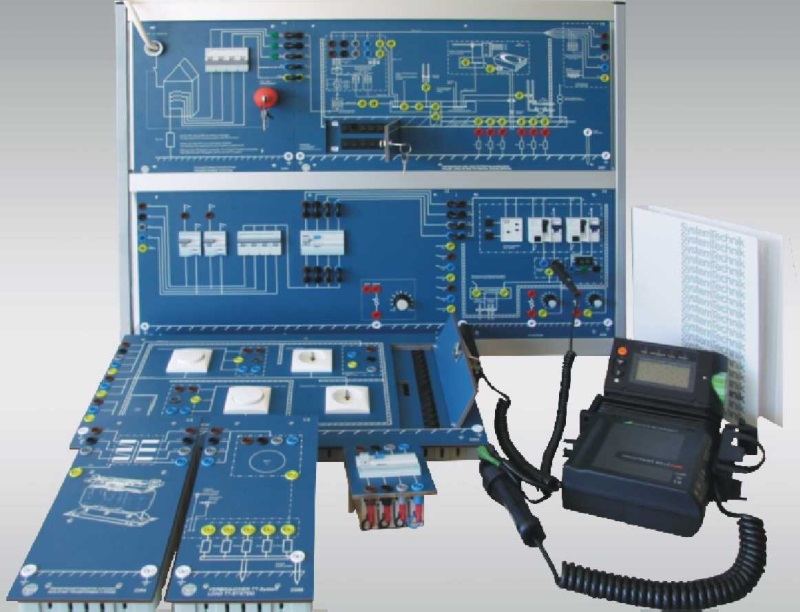
Type 2300
Electrical Safety Technology Series 2300
The teaching system is used for measurements in electrical protection measures and installation technology. It consists of seven teaching boards, an experiment manual and a standard test instrument, and is designed for direct measurements at 230 V / 400 V.
- Practical measurements with standard test equipment directly at 230 V / 400 V
- Standards-compliant testing of protective measures
- For 1- and 3-phase networks TN / TT / IT systems
- Clear arrangement of the components
- Switching common faults in protection and installation technology
- Lockable door
System Overview
The teaching system is used for measurements in the field of electrical protection measures and installation technology.
It consists of seven teaching boards, an experiment manual and any commercially available test instrument. Measurements are performed directly at 230 V / 400 V; tests according to country-specific standards are possible.
Teaching Boards and Modules
- Type 2350 - Transformer station supplying all teaching boards of the system; Cekon CEE connection; 4-pole MCB B6; output 230 V (phase / N) and 400 V (phase / phase); housing 266 x 297 x 100 mm; weight approx. 2.5 kg.
- Type 2351 - House and equipotential bonding; each phase can be switched; different networks shown; local equipotential bonding switchable; various earth resistances switchable; 12 faults switchable; earth probe for measurement with a standard meter.
- Type 2352 - Fuse box; replica of a domestic fuse box with 2 x combined protective switches, 4-pole MCB, replaceable 4-pole RCD and test potentiometer.
- Type 2353 - Apartment; replica of a four-room apartment; 15 faults switchable; cooker connection box with 4 mm safety sockets; sockets, switches and lamps integrated.
- Type 2354 - Isolation transformer; 3-phase 400 V / 50 ... 60 Hz; delta input, star output; screen winding to PE; galvanically isolated.
- Type 2355 - IT system; insulation monitoring with industrial insulation monitor; RCD and MCBs; socket, switch and lamp; potentiometer for RCD tests.
- Type 2356 - Consumer TT system; load board in TN / TT system with simulation of a 3-phase consumer, various earth resistances and an earth probe.
- Type 2352.1 - RCD protection switch 300 mA type A for the fuse box, exchangeable and with safety sockets brought out.
- Type 2352.2 - RCD protection switch 30 mA type B for the fuse box, all-current sensitive and exchangeable.
- Type 2352.3 - RCD protection switch 300 mA type A, selective; separate A-format board for upstream connection before the fuse box.
Recommended Accessories
For the experiments of the manual we recommend the conductor set Type 2350.1; it includes safety leads and safety connectors in different lengths and colours.
Any commercially available test instrument for measuring electrical protective measures can be used; the preferred device used for the manual was the Profitest SII+ / 0100.
- Type V 0119 - Experiment manual Electrical Safety Technology and Networks.
- Type 2350.1 - Conductor set: 6 x 1.5 m safety leads, 12 x 75 cm safety leads, 2 x 25 cm safety leads, 30 x safety connectors.
- Excellent for test and examination purposes
- Transformer separately fused
- Emergency stop switch
- Replaceable RCD protection switch type A, type A selective and type B all-current sensitive
- System scope
- 7 teaching boards, an experiment manual and a commercially available test instrument.
- Mains connection
- 3-phase 230 V / 400 V; 50 ... 60 Hz.
- Measurement mode
- Direct measurements at 230 V / 400 V; country-specific standards.
- Experiment manual
- V 0119
- Type 2350
- Transformer station; Cekon CEE standard; 4-pole MCB B6; output 230 V (phase / N) and 400 V (phase / phase); housing 266 x 297 x 100 mm; weight approx. 2.5 kg.
- Type 2351
- House and equipotential bonding; various networks and earth resistances switchable; 12 faults switchable; earth probe.
- Type 2352
- Fuse box; 2 x combined protective switches; 4-pole MCB; replaceable 4-pole RCD; test potentiometer.
- Type 2353
- Apartment; 4 rooms; 15 faults switchable; cooker connection box; sockets, switches and lamps integrated.
- Type 2354
- Isolation transformer; 3-phase 400 V / 50 ... 60 Hz; 150 VA.
- Type 2355
- IT system; insulation monitor; RCD; MCBs; potentiometer for RCD tests.
- Type 2356
- Consumer TT system; simulation of a 3-phase consumer and various earth resistances.
- Type 2352.1
- RCD 300 mA type A; 4-pole; exchangeable.
- Type 2352.2
- RCD 30 mA type B; all-current sensitive.
- Type 2352.3
- RCD 300 mA type A, selective; separate A-format board.
- 1 Safety notes when working with the boards1
- 2 Basic principles3
- 2.1 General3
- 2.2 Effects of electric current on the human body3
- 2.3 Duration of current exposure on the human body5
- 2.4 Electrical resistance of the human body6
- 2.5 Heart current factor6
- 2.6 Behavior in accidents7
- 2.7 Exercises7
- 2.7.1 Exercise 17
- 2.7.2 Exercise 27
- 3 Regulations9
- 3.1 General9
- 3.2 Installing electrical systems9
- 3.3 Structure of DIN VDE 010010
- 3.4 Overview of protective measures11
- 3.5 Recommended test devices13
- 3.6 Testing according to VDE 0100 group 60014
- 3.6.1 Inspection14
- 3.6.2 Testing and measuring14
- 3.6.3 Test report and handover report15
- 4 Terms and technical fundamentals17
- 4.1 Systems and networks17
- 4.2 Installation methods for cables and conductors19
- 4.3 Current carrying capacity of cables and conductors19
- 4.4 Permissible voltage drop21
- 4.5 Meter cabinet / meter position21
- 4.6 Equipotential bonding22
- 4.7 Earthing22
- 4.8 Fault types22
- 4.8.1 Earth fault current22
- 4.8.2 Fault voltage24
- 4.8.3 Maximum permissible touch voltage24
- 4.9 Overcurrent protection devices25
- 4.9.1 G fuses25
- 4.9.2 MCBs25
- 4.9.3 RCD, residual current protective device26
- 4.10 Network forms27
- 4.10.1 TN system27
- 4.10.2 TT system27
- 4.10.3 IT system28
- 4.11 Maximum permissible disconnection times29
- 4.12 Surge protection31
- 5 Measurement of voltages in TN-C system / TT system33
- 6 Measurement of protective and equipotential bonding conductors for continuity and low resistance35
- 6.1 Visual inspection35
- 6.2 Measurement of protective and equipotential bonding conductors and the earthing system37
- 6.3 Measurement of earth resistance40
- 6.3.1 Measurement of earth resistance with probe40
- 6.3.2 Measurement of earth resistance without probe42
- 6.3.3 Measuring earth potential44
- 7 Loop impedance, network impedance and short-circuit current47
- 7.1 General47
- 7.2 Measuring loop impedance, network impedance and short-circuit current48
- 8 Insulation resistance51
- 8.1 General51
- 8.2 Measuring insulation resistance52
- 9 Checking the phase sequence55
- 10 Checking the residual current circuit (RCD)57
- 10.1 Measuring touch voltage with 1/3 of the rated residual current and tripping test with rated current57
- 10.1.1 Measuring without probe57
- 10.1.2 Measuring with probe59
- 10.2 Measuring the tripping current of the residual current protective device60
- 11 Acceptance test of an apartment in TN system61
- 11.1 Visual inspection61
- 11.2 Continuity and low resistance of the protective and equipotential bonding conductors63
- 11.3 Measuring earth resistance64
- 11.4 Measuring voltages U N, U PE and U N-PE65
- 11.5 Measuring loop impedance and short-circuit current66
- 11.6 Measuring network impedance and short-circuit current67
- 11.7 Measuring insulation resistance68
- 11.8 Checking the phase sequence69
- 11.9 Measuring touch voltage, trip time and tripping current at the RCD70
- 11.10 Preparing the test report71
- 11.11 Fault finding in the electrical installation74
- 12 Acceptance test of an apartment in TT system75
- 12.1 Visual inspection75
- 12.2 Continuity and low resistance of the protective and equipotential bonding conductors77
- 12.3 Measuring earth resistance78
- 12.4 Measuring voltages U N, U PE and U N-PE79
- 12.5 Measuring loop impedance and short-circuit current80
- 12.6 Measuring network impedance and short-circuit current81
- 12.7 Measuring insulation resistance82
- 12.8 Checking the phase sequence83
- 12.9 Measuring touch voltage, trip time and tripping current at the RCD84
- 12.10 Preparing the test report85
- 12.11 Fault finding in the electrical installation88
- 13 TN system with directly earthed load89
- 13.1 Visual inspection89
- 13.2 Measuring voltages U N, U PE and U N-PE91
- 13.3 Measuring loop impedance and short-circuit current92
- 13.4 Measuring network impedance and short-circuit current93
- 13.5 Measuring insulation resistance94
- 13.6 Checking the phase sequence95
- 13.7 Measuring touch voltage, trip time and tripping current at the RCD96
- 14 IT system97
- 14.1 General97
- 14.2 Insulation monitor97
- 14.3 Testing the insulation monitor98
- 14.4 Measuring all voltages in the IT system99
- 14.5 Measuring trip time and tripping current at the RCD100
- 14.6 Single fault in the IT system101
- 14.7 Multiple faults in the IT system103
Taken from the tables of contents of the hps experiment manuals (titles, numbers and pages). All manuals are German; titles are shown in the original language. All manuals and experiments
V 0117 Elektrische Schutztechnik und Netzsysteme Manual · 110 pages 74 experiments
Main device of this manual – applies to all experiments View table of contents
- 2.7.1 Übung 1 p. 7
- 2.7.2 Übung 2 p. 7
- 3.2 Errichten elektrischer Anlagen p. 9
- 3.4 Übersicht über die Schutzmaßnahmen p. 11
- 3.5 Empfohlene Prüffristen p. 15
- 3.6.1 Besichtigen p. 14
- 3.6.2 Erproben und Messen p. 14
- 3.6.3 Prüfprotokoll und Übergabebericht p. 15
- 4.1 Anlagen und Netze p. 17
- 4.2 Verlegearten für Kabel und Leitungen p. 18
- 4.3 Strombelastbarkeit von Kabeln und Leitungen p. 19
- 4.4 Zulässiger Spannungsfall p. 21
- 4.5 Zählerschrank / Zählerplatz p. 21
- 4.6 Potentialausgleich p. 22
- 4.7 Erdung p. 22
- 4.8.1 Fehlerstrom p. 22
- 4.8.2 Fehlerspannung p. 24
- 4.8.3 Maximal zulässige Berührungsspannung p. 24
- 4.9.1 G-Sicherungen p. 25
- 4.9.2 LS-Schalter p. 25
- 4.9.3 RCD, Fehlerstrom-Schutzeinrichtung p. 26
- 4.10.1 TN-System p. 27
- 4.10.2 TT-System p. 27
- 4.10.3 IT-System p. 28
- 4.11 Maximal zulässige Abschaltzeiten p. 29
- 4.12 Überspannungsschutz p. 31
- 5.1 Messung der Spannungen im TN-C System / TT-System p. 33
- 6 Messung der Schutz- und Potentialleierausgleichsleiter auf Durchgängigkeit und p. 35
- 6.1 Sichtprüfung p. 35
- 6.2 Messung der Schutz- und Potentialleierausgleichsleiter und der Erdungsanlage p. 37
- 6.3.1 Messung des Erdungswiderstandes mit Sonde p. 40
- 6.3.2 Messung des Erdungswiderstandes ohne Sonde p. 41
- 6.3.3 Messen der Erderspannung p. 44
- 7.2 Messung der Schleifenimpedanz, Netzimpedanz und des Kurzschlussstromes p. 48
- 8.2 Messen des Isolationswiderstandes p. 52
- 9 Prüfen der Drehfeldrichtung p. 55
- 10.1.1 Messen ohne Sonde p. 57
- 10.1.2 Messen mit Sonde p. 59
- 10.2 Messen des Auslösestroms bei der Fehlerstrom-Schutzschaltung p. 60
- 11.1 Sichtprüfung p. 61
- 11.2 Durchgängigkeit und Niederohmigkeit der Schutz- und Potentialausgleichsleiter p. 63
- 11.3 Messen des Erdungswiderstandes p. 64
- 11.4 Messen der Spannungen UL-N, UL-PE und UN-PE p. 65
- 11.5 Messen der Schleifenimpedanz und des Kurzschlussstromes p. 66
- 11.6 Messen der Netzimpedanz und des Kurzschlussstromes p. 67
- 11.7 Messen des Isolationswiderstandes p. 68
- 11.8 Messen der Drehfeldrichtung p. 69
- 11.9 Messen der Berührungsspannung, der Auslösezeit und des Auslösestromes beim p. 70
- 11.10 Erstellen des Abnahmeprotokolls p. 71
- 11.11 Fehlersuche in der elektrischen Anlage p. 74
- 12.1 Sichtprüfung p. 76
- 12.2 Durchgängigkeit und Niederohmigkeit der Schutz- und Potentialausgleichsleiter p. 77
- 12.3 Messen des Erdungswiderstandes p. 78
- 12.4 Messen der Spannungen UL-N, UL-PE und UN-PE p. 79
- 12.5 Messen der Schleifenimpedanz und des Kurzschlussstromes p. 80
- 12.6 Messen der Netzimpedanz und des Kurzschlussstromes p. 81
- 12.7 Messen des Isolationswiderstandes p. 82
- 12.8 Messen der Drehfeldrichtung p. 83
- 12.9 Messen der Berührungsspannung, der Auslösezeit und des Auslösestromes beim p. 84
- 12.10 Erstellen des Abnahmeprotokolls p. 85
- 12.11 Fehlersuche in der elektrischen Anlage p. 88
- 13.1 Messen des Erdungswiderstandes p. 90
- 13.2 Messen der Spannungen UL-N, UL-PE und UN-PE p. 91
- 13.3 Messen der Schleifenimpedanz und des Kurzschlussstromes p. 92
- 13.4 Messen der Netzimpedanz und des Kurzschlussstromes p. 93
- 13.5 Messen des Isolationswiderstandes p. 94
- 13.6 Messen der Drehfeldrichtung p. 95
- 13.7 Messen der Berührungsspannung, der Auslösezeit und des Auslösestromes beim p. 96
- 14.2 Isolationswächter p. 97
- 14.3 Prüfen des Isolationswächters p. 98
- 14.4 Messen sämtlicher Spannungen im IT-System p. 99
- 14.5 Messen der Auslösezeit und des Auslösestroms beim RCD p. 100
- 14.6 Einzelner Fehler im IT-System p. 101
- 14.7 Mehrfachfehler im IT-System p. 103
No experiment matches the filter.
V 0117 Elektrische Schutztechnik und Netzsysteme Solutions · 31 pages 0 experiments
Main device of this manual – applies to all experiments View table of contents
No experiment matches the filter.


